App. A Advantageous Use of Inverters (Notes on Electrical Noise)
A-3
App.
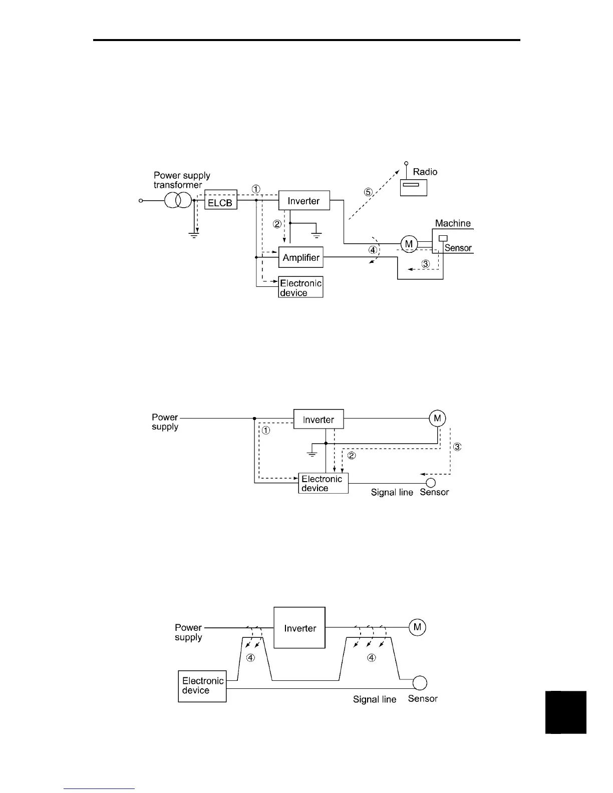
[2] Type of noise
Noise generated in an inverter is propagated through the main circuit wiring to the power supply and the
motor so as to affect a wide range of applications from the power supply transformer to the motor. The
various propagation routes are shown in Figure A-2. According to those routes, noises are roughly
classified into three types; conduction noise, induction noise, and radiation noise.
c to e are conduction noises, f is induction noise, and g is radiation noise. The following provides the
details of the function codes.
Figure A-2 Noise Propagation Route
(1) Conduction Noise
Noise generated in an inverter may propagate through the conductor and power supply so as to affect
peripheral devices of the inverter (Figure A-3). This noise is called "conduction noise." Some conduction
noises will propagate through the main circuit c. If the ground wires are connected to a common ground,
conduction noise will propagate through route d. As shown in route e, some conduction noises will
propagate through signal lines or shielded wires.
Figure A-3 Conduction Noise
(2) Induction Noise
When wires or signal lines of peripheral devices are brought close to the wires on the input and output sides
of the inverter through which noise current is flowing, noise will be induced into those wires and signal lines
of the devices by electromagnetic induction (Figure A-4) or electrostatic induction (Figure A-5). This is
called "induction noise" f.
Figure A-4 Electromagnetic Induced Noise

 Loading...


