2.2 Wiring
2-36
SW5
<Switches the property of the analog input terminal
[V2]>
This switches the property of the terminal between analog setting voltage input, PTC
thermistor input, and NTC thermistor input. When changing this switch setting, also
change the data of function code H26.
Table 2.2-23
SW5 Set data of H26 to:
Analog setting current
input
(Factory default)
V2 0
PTC thermistor input PTC/NTC 1 (alarm) or 2 (warning)
NTC thermistor input PTC/NTC 3
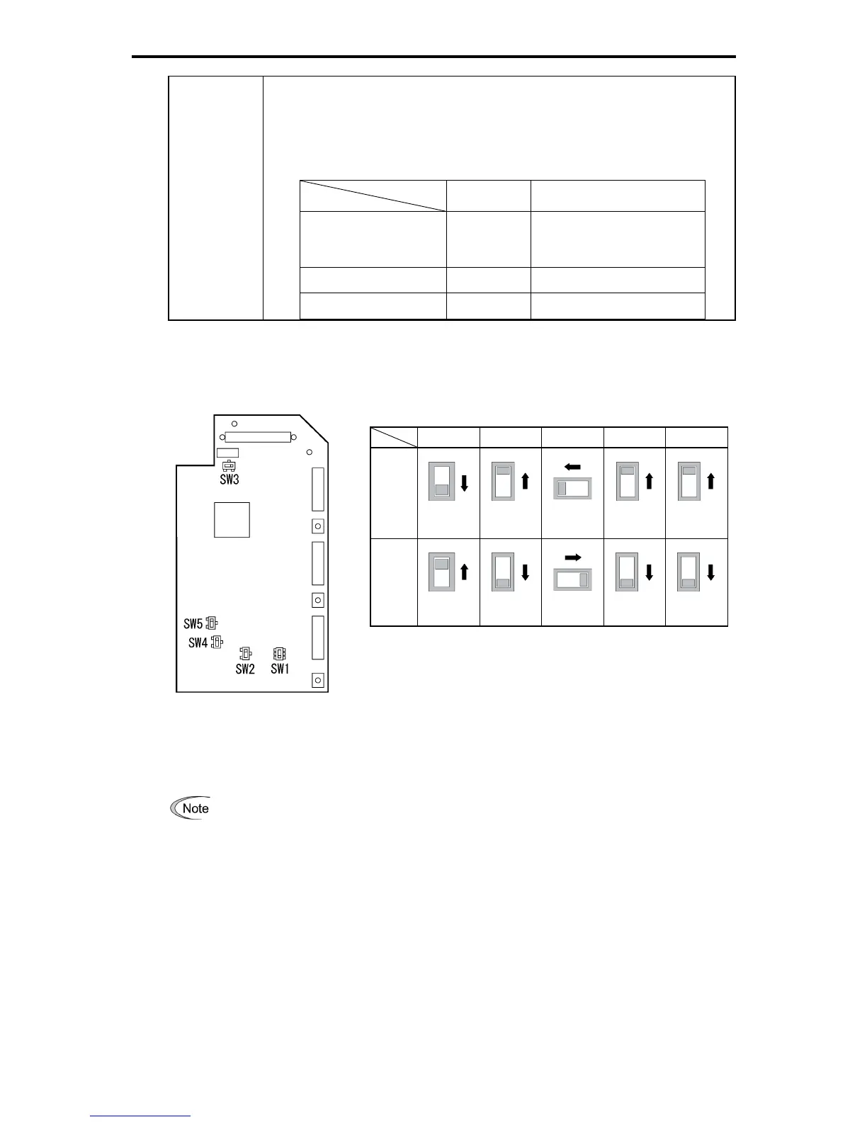
The following diagram shows the location of slide switches on the control PCB.
Figure 2.2-30 Location of the
Slide Switches on the Control
PCB
Table 2.2-24 Switching Examples and Factory Default
SW1 SW2 SW3 SW4 SW5
Factory
default
SINK
OFF
OFF
VO
V2
-
SOURCE
ON
ON
IO
PTC/NTC
To move a switch slider, use a tool with a narrow tip (e.g., tweezers), taking care not to touch
other electronic parts on the PCB. If the slider is in an ambiguous position, the circuit is unclear
whether it is turned ON or OFF and the digital input remains in an undefined state. Be sure to
place the slider so that it contacts either side of the switch.
Output mode

 Loading...


