ENGLISH Use e Maintenance
ment tie rod (3, Fig. 4.2) make sure that when the
machine is in work position (see § 4.7.1 on the 27), it
is perpendicular to the ground (Fig. 4.2).
3. Block the movement of the parallels of the tractor on
the horizontal plane using the stabilizers provided, so
eliminating the side swaying of the equipment. Check
that the tractor hoisting arms are positioned at the
same height from the ground.
4. Connect the cardan shaft and make sure that it is per-
fectly blocked on the power take-off (Fig.4.3). Check
that the guard turns freely and fix it with the chain
provided. Working under these conditions limits the
stress on the power take-off itself and prolongs the
duration of the Cardan shaft and the machine itself.
5. Connect the electrical plugs for the electronic control
system.
6. Connect the electrical plug for the rear road lights.
7. Lift and remove the storage wheels (optional).
4.1.2 Unhooking the machine from the
tractor
DANGER!
Unhooking the machine from the tractor is a very
dangerous operation. Great caution must be used and
the whole operation must be carried out following the
instructions.
1. Attach the storage wheels (optional). See §
4.7.11.
2. Lower the machine slowly until it is completely
resting on the ground. See § 4.7.11.
3. Disconnect the electrical plugs for the electronic con-
trol systems and protect them with the specific caps.
4. Disconnect the electrical plug for the rear road lights.
5. Unhook the Cardan shaft from the tractor and place
it on the provided hook.
6. Loosen and unhook the third point, following the first
and second.
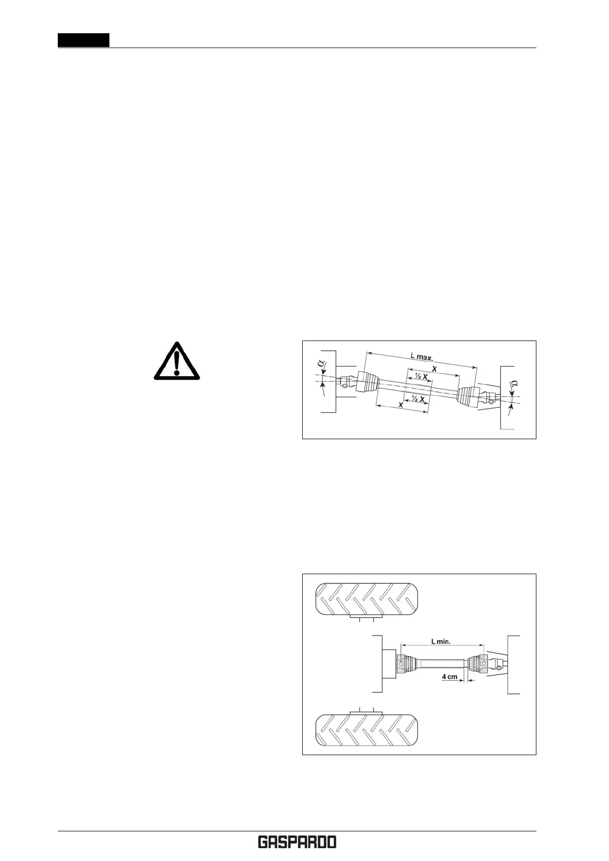
4.2 ADAPTING THE CARDAN
SHAFT
The Cardan shaft, supplied with the machine, is of stan-
dard length. It might, therefore, be necessary to adapt the
cardan shaft. Should this be the case, before proceeding,
consult the Manufacturer.
1. Hitch the machine to the tractor and stabilize the trac-
tor’s third point with the device installed for that pur-
pose (bar, chain, etc.). Connection is correct when
the machine is horizontal in the operating position.
2. Turn off the engine, engage the parking brake, re-
move the ignition key from the control panel and en-
sure that nobody can get near the assembly.
3. Connect the driveline shaft to the tractor’s PTO. Con-
nection is correct when the machine is horizontal in
the operating position. To achieve this, increase or
decrease the length of the top bar of the hitch.
Check length prior in order to prevent:
• If too long: HARMFUL THRUSTS ON THE MACHINE
SHAFT.
• If too short: POSSIBILITY OF DANGEROUS
BREAKAGE OR SLIPPAGE OF THE PTO SHAFT.
Inspections at work:
• The two angles (α) formed by the fork axes and the
axis of the sliding tubes will be equal and must not
exceed 10
◦
.
• Telescoping tubes must always overlap by at
least 1/2 of their length in normal operation and
at least 1/3 of their length in all working condi-
tions. During maneuvers, when the driveline is
not rotating, the telescoping tubes must have a
suitable overlap to maintain the tubes aligned and
allow then to slide freely.
Inspections in the raised position:
• Proceed with a lifting action (tractor PTO disen-
gaged).
• The two tubes of the driveline shaft must not fully
overlap. There must always be a safety travel of at
least 4 cm.
• The angles (α) of the drivelines must not exceed 40
◦
.
22- EN Cod. F07011577