Use e Maintenance ENGLISH
4.7.3 Removing and replacing the
spreading discs
DANGER!
All operations must be done exclusively with the
tractor off, P.T.O. disengaged, parked with
parking brake and with the key removed.
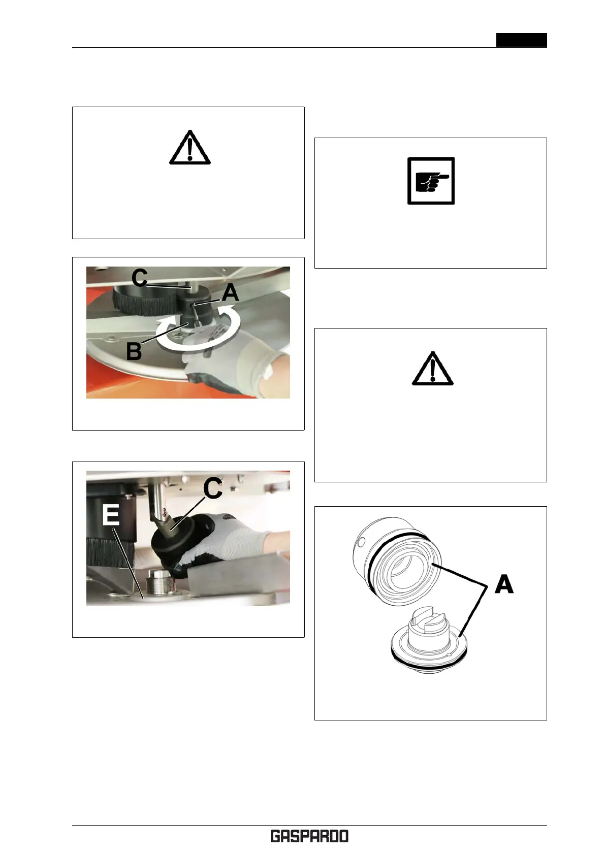
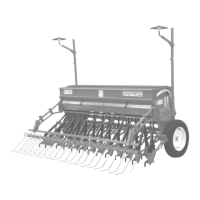
Figure 4.18: Removing the spreading disc - 1
Figure 4.19: Removing the spreading disc - 2
To replace the spreading discs, refer to figures 4.18 and
4.19 and proceed as instructed below.
1. Insert the specific tool in the locking handwheel hous-
ing (A) .
2. Completely loosen the locking handhweel (B). To
loosen the locking handwheel, you must turn it in the
same direction as spreading disc rotation. As such, to
remove the right disc, the handwheel must be turned
anticlockwise, while to remove the left disc, the hand-
wheel must be turned clockwise.
3. Slide the locking handwheel along the shaft (C).
4. Turn the agitator drive shaft (C) outward.
5. Pull the spreading disc (E) upwards and remove it.
To reassemble the new spreading discs, repeat the
above operations in reverse order.
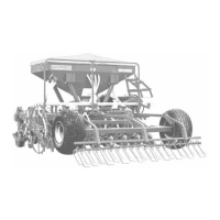
Do not confuse the right handwheel with the left
one. They have opposite threading and if dam-
aged, they can jeopardise safe use of the ma-
chine!
The right handwheel and the fastening unit to which it is
paired are marked by a specific round notch (A) as shown
in Fig. 4.20
DANGER!
Danger of parts being ejected from the machine.
After replacing the spreading discs, make sure
the locking handwheel has been tightened
appropriately and that no foreign objects have
been left on the spreading discs.
Figure 4.20: Notch identifying the right hand-
wheel and its fastening unit
4.7.4 Inner grid opening
Cod. F07011577 EN - 31