ENGLISH Use e Maintenance
1. Before starting, make sure the electric actuator is in
the all-closed position (stem completely retracted).
Consult the control system instructions manual for
this operation.
2. Remove the retaining ring (1), slide out the pin (2)
and free the electrical actuator (8).
3. Loosen the fastening screw (7) on the electrical actu-
ator (8).
4. Insert a calibrated pin (5mm) (3) into the hole (4) ) of
the dosing shutter (6) until it catches the hole in the
support plate (5) .
5. Reposition the electrical actuator (8), the pin (2) ) and
the ring (1). During this operation, the locking pin (9)
will find a new position naturally.
6. Tighten the fastening screw (7). Use an appropri-
ate threadlocker to prevent the screw (7) from coming
loose.
7. Slide out the calibrated pin (3).
Do the operations described on both dosing shutters.
5.6 CALIBRATING THE DROP
POINT
If you notice the machine spreading the fertiliser asymmet-
rically (see § 4.7.9) you may need to check proper drop
point positioning.
Figure 5.3: Calibrating the drop point
With reference to fig 5.3 to calibrate the drop point, pro-
ceed as follows.
1. Use the lever (1) and turn the drop point until the
calibrated pin (5mm) (3), locks drop point rotation by
passing through the hole .
2. Then make sure the indicator (2) points to the "30"
position. If necessary, loosen the fastening screws
(5) and properly reposition the graduated scale (7).
3. Tighten the screws (5) and remove the pin (1).
Do the operations described on both drop point adjust-
ments.
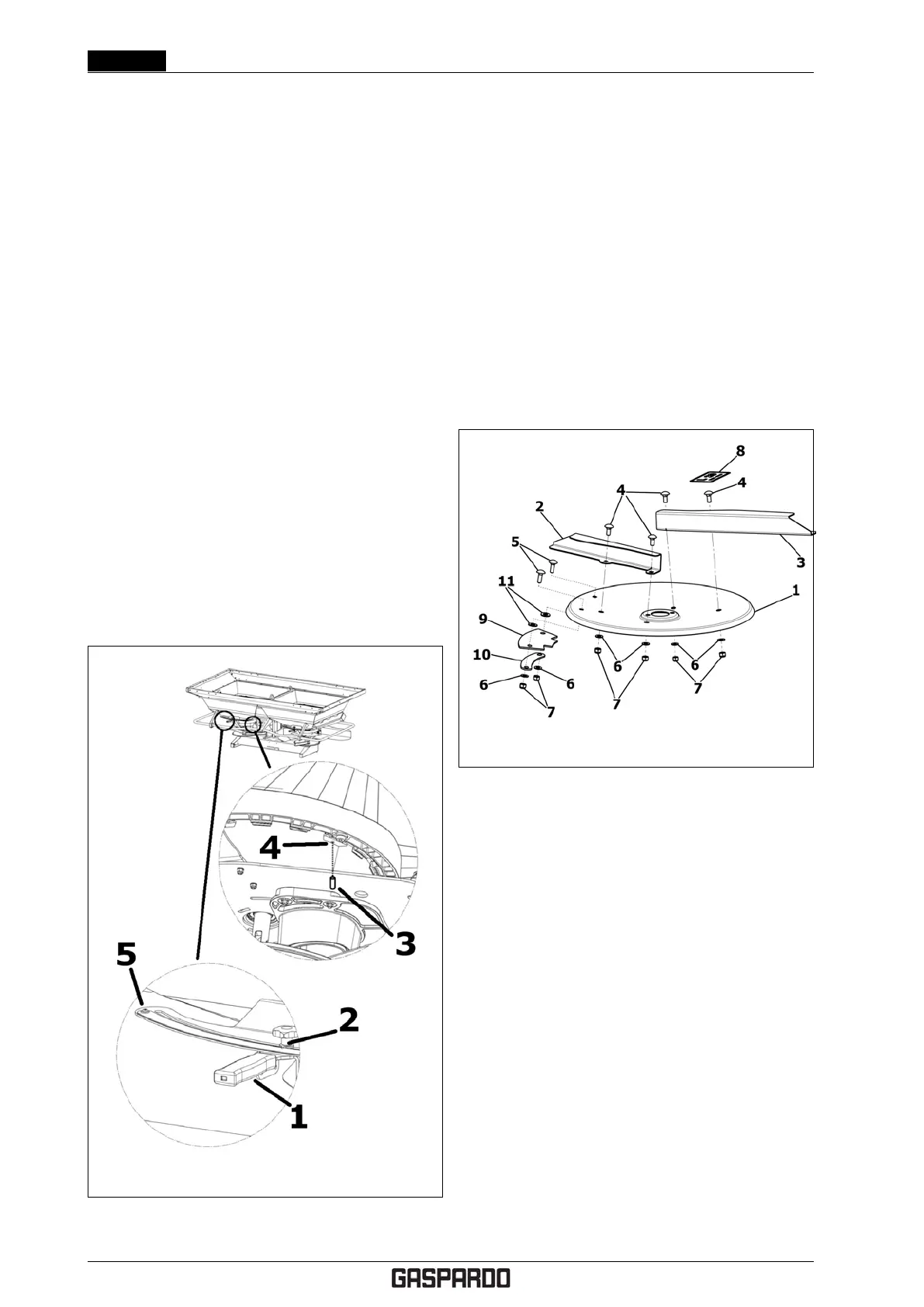
5.7 REPLACING THE SPREAD-
ING VANES
Figure 5.4: Replacing the spreading vanes
If they are damaged or worn, the spreading vanes can
be replaced.
With reference to fig 5.4 proceed as follows.
1. Remove the spreading disc (see § 4.7.3).
2. Loosen the fastening screws (4).
3. Replace the old vanes with the new ones, being care-
ful not to invert the assembly direction.
4. Tighten the spreading vane, always using new
screws (4) and self-locking nuts (7).
5.8 CHECKING THE DRIVE HUB
POSITION
The drive hub must always be aligned with the agitator
drive shaft.
With reference to fig. 5.5 proceed as follows.
1. Remove the spreading disc and slide out the locking
handhweel.
2. Position the drive hub in position (A) and make sure
the agitator shaft is able to feely enter the groove.
42- EN Cod. F07011577