Use e Maintenance ENGLISH
transfer zone. Check the state, condition and suitabil-
ity of the means at disposition. Do not touch sus-
pended loads, keeping them at a safe distance.
It most be further ascertained that the operational
area is free of obstacles and that there is sufficient
«escape space», meaning an area which is free and
secure into which one could move rapidly in case a
load should fall.
The surface on which the machine is to be loaded
must be horizontal in order to prevent possible shift-
ing.
Once the machine is positioned on the vehicle, make
sure that it remains blocked in its position. Fasten the ma-
chine on the platform of the vehicle by means of cables
suitable for the mass which must be blocked (see «Tech-
nical Data» on pag. 16 for the weight).
The cables must be firmly fastened to the machine and
pulled taut to the anchorage point on the platform.
Once transport has been carried out and before freeing
the machine from all its fastenings, make sure that its state
and position are such as not to constitute danger.
Remove the cables and proceed to unloading with the
same means and methods used for loading.
Transit and transporting on the public highways
When driving on the public roads, fit on the rear re-
flector triangles, side lights and fl ashing beacon and
always make sure that you comply with the Highway Code
and any other applicable regulations.
Make sure that the machine dimensions during transfer
phases allow for safe transport when travelling in subways,
along narrow roads, near electrical lines, etc.
ATTENTION!
Maximum speed when transporting the machine on
the road is 25 km/h.
Before driving on to the public roads with the ma-
chine hitched to the tractor, make sure that the de-
vices listed above and/or the slow vehicle signal
and/or the projecting load signal operate correctly.
These indicators must be affixed to the rear of the im-
plement in a position where they can be clearly seen
by any other vehicle that drives up behind.
The tractor used for transporting the equipment must
have the powers shown in the Technical Data table, if nec-
essary, redistribute the total weights with the addition of
ballasts to return balance and stability to the whole as-
sembly (see § 4.3 pag. 22).
For displacements beyond the work area, the equip-
ment must be placed in the transportation position:
• Where provided for, make all the moving parts come
within the transport width, locking them with the
safety devices.
• Any transport accessories must be provided with suit-
able signs and guards.
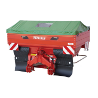
• The fertiliser spreader must be empty.
4.5 MACHINES SUPPLIED
PARTLY BROKEN-DOWN
Owing to their size, the machines may be supplied with
detached parts, always fixed in the same pack.. Usu-
ally, the group of raisers to expand hopper capacity are
detached and later assembled by the customer.
Execute these installation operations with the ut-
most care. Refer to the list of parts in the Spare Parts
Catalogue. In particular, apply the screw tightening
torques as listed in the Chart on following pages.
4.6 BEFORE USE
Before starting the machine, check that:
• The machine is perfectly in order, that the lubricants
are at the correct levels (see chap. 5 «Manuten-
zione» on pag. 39) and that all parts subject to wear
and deterioration are fully efficient.
Mounting of the accident prevention guards
Using the pipe clamps and fastening screws, secure the
protection bar in points (A), (B), (C), (D) (E), as shown in
figure (4.6).
Before tightening the fastening screws all the way, make
sure that the distance between the machine and the pro-
tection bar is as shown in figure (4.7).
If assembling the limiter accessory for border spreading,
the protection bar must be replaced with the two bars (A)
and (B) shown in figure (4.8), the fastening points are the
same.
Respect the installation heights shown in the figure be-
fore tightening the fastening screws all the way. Should
it not be possible to close the spaces as listed above or
should the protections be damaged, immediately order
new ones, communicating the machine identification se-
rial number.
Assembling the hopper extensions
The machine is usually delivered with the base hopper ex-
tensions disassembled. To assemble the hopper exten-
sions, refer to the exploded drawings in the spare parts
tables and proceed as follows.
1. Apply the adhesive gasket all along the edge of the
base hopper (A: Fig. 4.10) keeping a distance of
about 5mm from the edge, as shown in Fig. 4.9.
2. Position the base extensions (Ba), (Bb) (C), cas
shown in Fig. 4.10. Tighten the fastening screws only
after having readied all the extensions.
3. Proceed in the same way to assemble the upper ex-
tensions (see Fig. 4.11) inserting the adhesive gas-
ket between one extension and another.
4. Complete extension assembly by applying the inner
tie rods (D1) and (D2) (see Fig. 4.11).
Cod. F07011577 EN - 25