Use e Maintenance ENGLISH
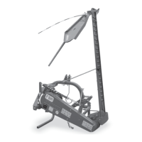
Figure 4.8: Protection kit for machines with bor-
der deflector
Assembling the hopper extensions
The machine is usually delivered with the base hopper ex-
tensions disassembled. To assemble the hopper exten-
sions, refer to the exploded drawings in the spare parts
tables and proceed as follows.
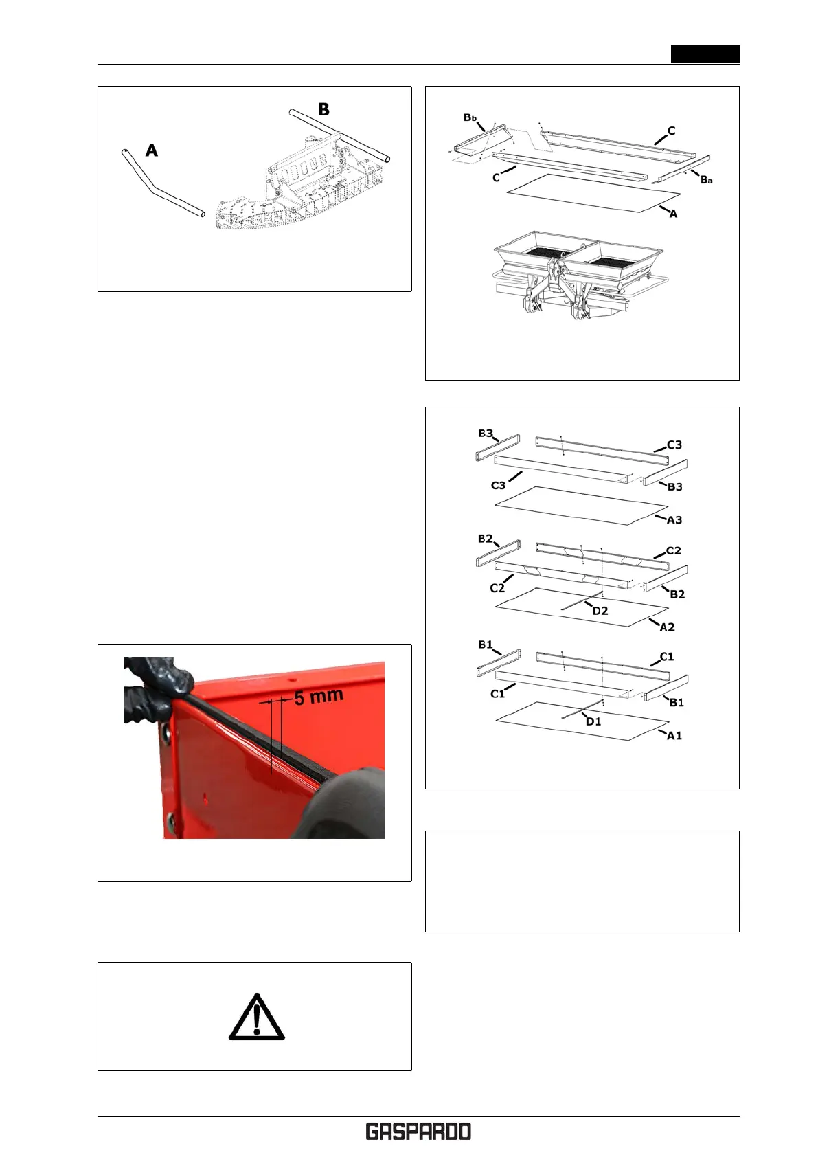
1. Apply the adhesive gasket all along the edge of the
base hopper (A: Fig. 4.10) keeping a distance of
about 5mm from the edge, as shown in Fig. 4.9.
2. Position the base extensions (Ba), (Bb) (C), cas
shown in Fig. 4.10. Tighten the fastening screws only
after having readied all the extensions.
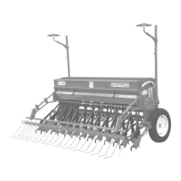
3. Proceed in the same way to assemble the upper ex-
tensions (see Fig. 4.11) inserting the adhesive gas-
ket between one extension and another.
4. Complete extension assembly by applying the inner
tie rods (D1) and (D2) (see Fig. 4.11).
Figure 4.9: Applying the adhesive gasket
Installing the Cardan shaft
WARNING!
Figure 4.10: Assembling the base extensions
Figure 4.11: Assembling the upper extensions
Only use Cardan shafts approved by the
manufacturer.
Read and follow the instructions in the Cardan
shaft manufacturer instructions manual.
The machine is supplied with the Cardan shaft disassem-
bled.
To assemble the Cardan shaft, proceed as follows.
1. Grease the fertiliser spreader grooved shaft.
2. Insert the Cardan shaft until the safety pin clicks (see
Fig. 4.12). Respect the assembly direction: the
picture of the tractor must be facing toward the
tractor!
Cod. F07011577 EN - 27