Use e Maintenance ENGLISH
If these two results are not obtained:
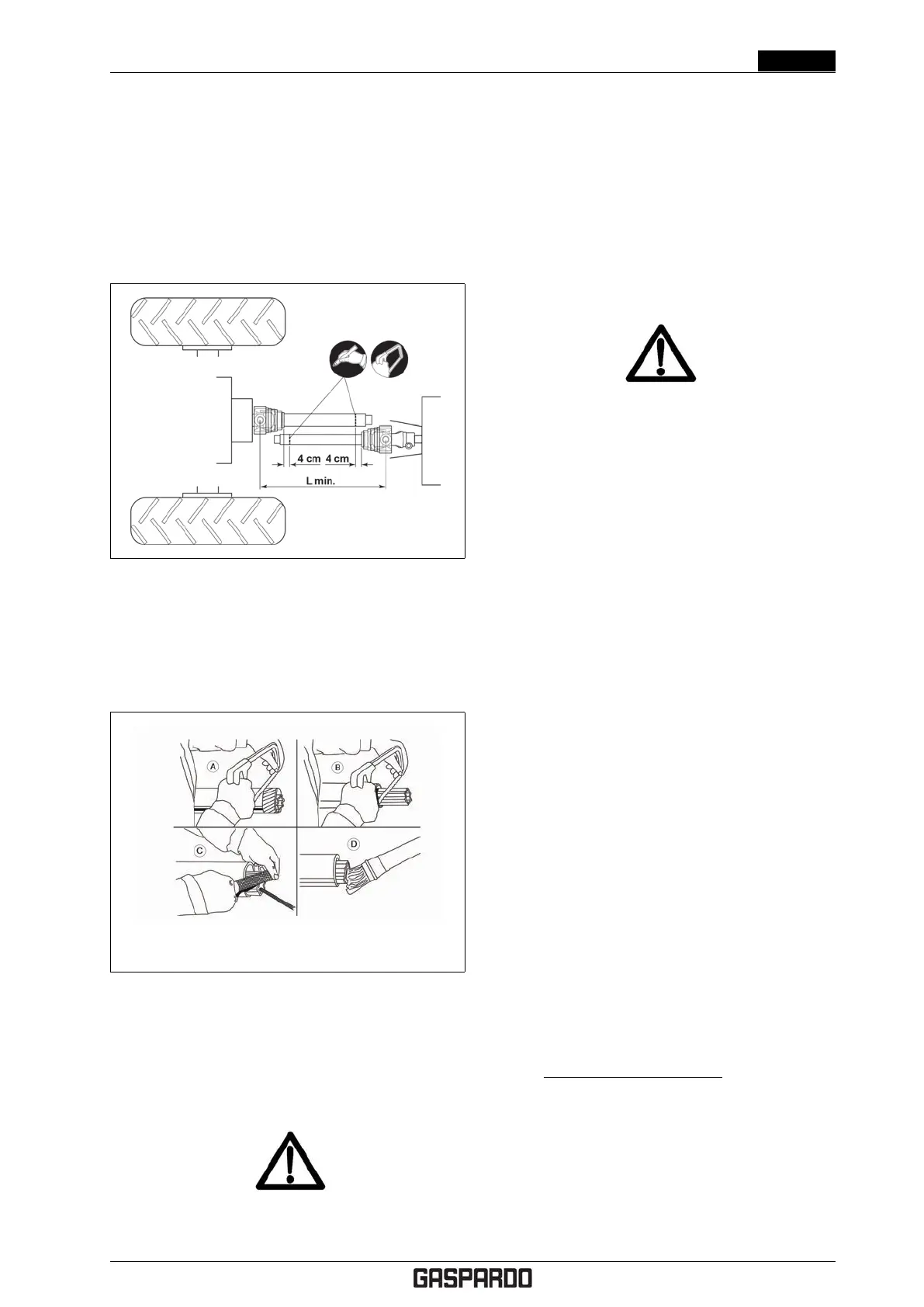
1. Extend the telescopic tubes completely, insert a tube
on the tractor PTO and the other on the machine.
Make sure that the telescopic tubes are locked per-
fectly.
2. Approach the telescopic tubes of the driveline and
fi nd the cutting position, taking into account the 4
cm of minimum safety clearance to guarantee against
breakage.
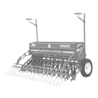
3. Shorten the telescopic tubes to the detected position
(A-B, 4.4) (the excess part must be the same length
on both tubes), trim and clean (C, 4.4) and grease the
inside of the external tube (D, 4.4).
4. Couple the telescopic tubes and engage the entire
driveline on the PTO.
Figure 4.4
5. Make sure that the upper hitch bar is as parallel as
possible to the lower bars of the hitch.
If this is not sufficient, correct the way the top link of the
hitch couples to the tractor or machine, as necessary, or at
least considerably attenuate, the jolts to which the driveline
shaft is subjected during the lifting phase.
CAUTION!
• Telescoping tubes must always overlap by at
least 1/2 of their length in normal operation and at
least 1/3 of their length in all working conditions.
When it is inserted all the way, the minimum ad-
missible play is 4 cm.
• When using the equipment on another tractor,
check that conditions are as stated above and
check that the guards complete ly cover the ro-
tating parts of the Cardan shaft.
The spare parts must correspond to the manufac-
turer’s specifi cations. Use only original spares.
ATTENTION!
Assemble, operate and disconnect the cardan shaft
always according to information and safety standards
supplied for shaft use, contained in the manual pro-
vided by the shaft manufacturer and delivered with the
shaft itself.
Each cardan shaft is equipped with a use and main-
tenance manual. Always carefully follow information
and safety standards supplied for shaft use as con-
tained in the manual.
Any damage to the machine and/or persons or prop-
erty arising from failure to adhere to the above and
incorrect use of the PTO shaft are not attributable
to MASCHIO GASPARDO S.p.A. and not recognisable
under warranty.
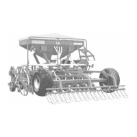
4.3 STABILITY OF PLANTING
UNIT AND TRACTOR DUR-
ING TRANSPORT
When a planting unit is coupled to a tractor, so becoming
an integral part of it for the purposes of road travel, the
stability of the planting unit-tractor complex may change
and cause driving or operating difficulties (rearing up or
side-slipping of the tractor). The condition of equilibrium
can be restored by placing a sufficient number of ballasts
on the front of the tractor so that the weights on the two
tractor axles are distributed sufficiently evenly. To work in
safety the instructions given in the highway code should be
followed; these prescribe that at least 20% of the weight
of the tractor alone should be borne by the front axle and
that the weight on the arms of the hoist should not be more
than 30% of the weight of the tractor itself. These factors
are summarized in the following formulas:
Z >
[M · (S1 + S2)] − (0.2 · T · i)
d + i
[kg] (4.1)
The symbols have the following meanings (please see
Fig. 4.5 for reference):
• M (kg)Mass weighing on arms off hoist with full load
(weight + mass, see cap 1.3 Identification on pag. 9).
• T (kg) Mass of tractor.
Cod. F07011577 EN - 23