Chapter 7: Repair Procedures
Canopy Removal for Service
Service Manual 7-7
Note: The cutouts in the north seal may be used to help with this positioning of these washers as shown in
the following figure:
c. Thread the set screw into the threaded hole in the guide rail near the “E” or “W” inscription. Refer to
Figure 7-7. The socket of the set screw should be on the outside of the canopy.
d. At the middle position of the long canopy sides, install the longer screw, lockwasher, spacer
washer, gasket, door support, and smooth nut, as shown in Figure 7-7.
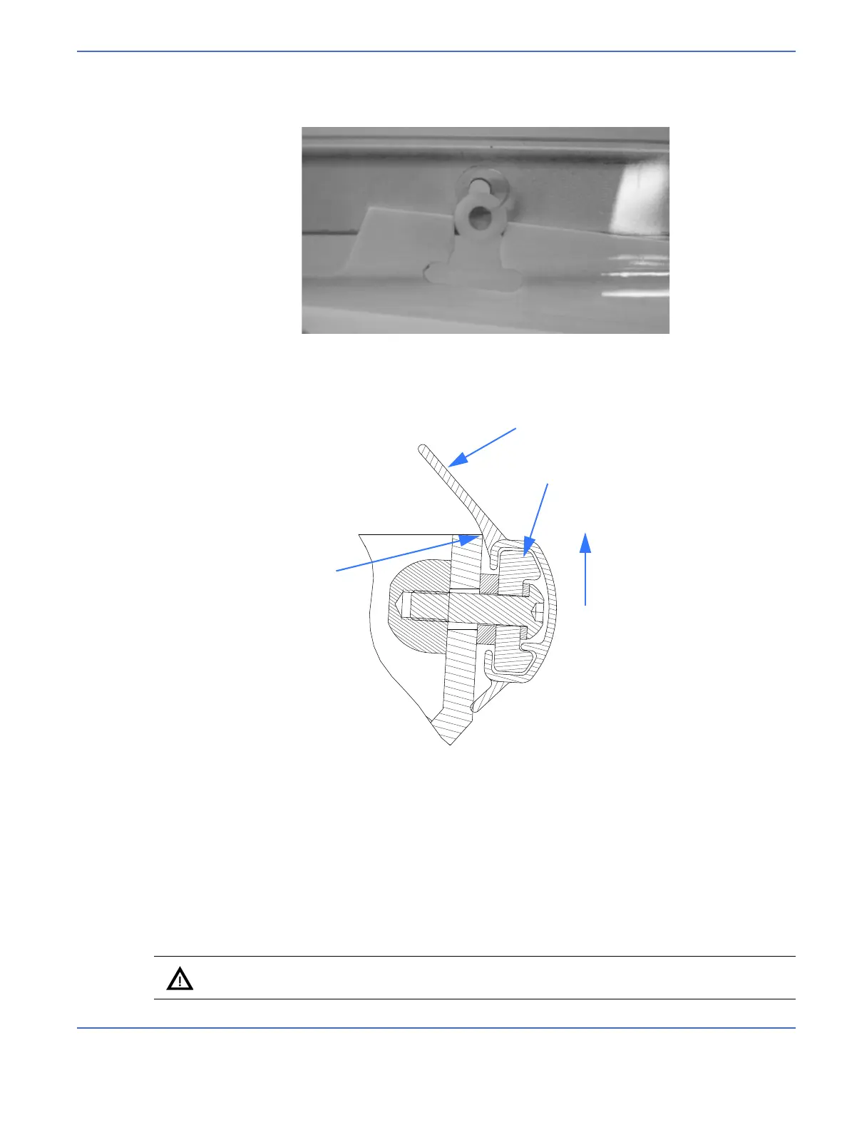
e. Slide the seals on both sides, for alignment purposes. Lift the seal assembly to the upper limit of
the canopy holes. Refer to Figure 7-9.
f. Using a 10 mm open-end wrench, tighten all nuts and screws until they feel snug.
g. Remove seal and verify that the lock washers are compressed flat. If necessary, tighten with
10mm open-end wrench and 2.5 mm hex key.
Caution: Do not over-tighten the hardware.
FIGURE 7-8. Using North Seal to Help Position Washers
FIGURE 7-9. Seal Cross-section
Canopy edge
Long lip of seal
Larger lobe
Lift assembly to upper limit of canopy holes.
INSIDE OF CANOPY
OUTSIDE OF CANOPY
NOTE: The canopy
is upside-down.

 Loading...


