Chapter 7: Repair Procedures
Servo Controlled Oxygen Service Procedures
Service Manual 7-61
7.18.3 Sensor Housing Repairs
7.18.3.1 Sensor Housing Repairs: Boards, Calibration Fan Assembly, and Sensor Plug Assembly
1. Slide the drawer to one side and using a 3 mm hex key, loosen the captive screws in the chassis cover
sensor housing door and swing the door down to access the sensor housing.
2. Using a 3 mm hex key, loosen the two M4 socket head screws that secure the sensor housing cover,
and remove the cover.
3. To replace the half of the PC board inside the sensor housing cover, use 2.5 mm hex key to remove the 2
M4 button head screws that secure it to the cover.
4. To replace the half of the PC board inside the sensor housing, disconnect from the wire harness and
remove the single M4 button head screw that holds it to the housing. Perform the Pre-use Checkout.
5. To replace the calibration fan, disconnect its electrical connector and remove the 4 self tapping screws
that secure it to the sensor housing. Install replacement fan so flow arrow on side points up into
chassis. Perform the Pre-use Checkout.
IMPORTANT: Fan orientation is critical to proper operation.
6. To replace sensor housing plug assembly, disconnect it from the sensor cable, and use a 7/16” open
wrench to unscrew it from the housing, then disconnect its other electrical connector. In addition to
taking static sensitive precautions, take care not to touch the sensor portion of the assembly with your
fingers to avoid contaminating it. After you replace the plug assembly, perform the Pre-use Checkout.
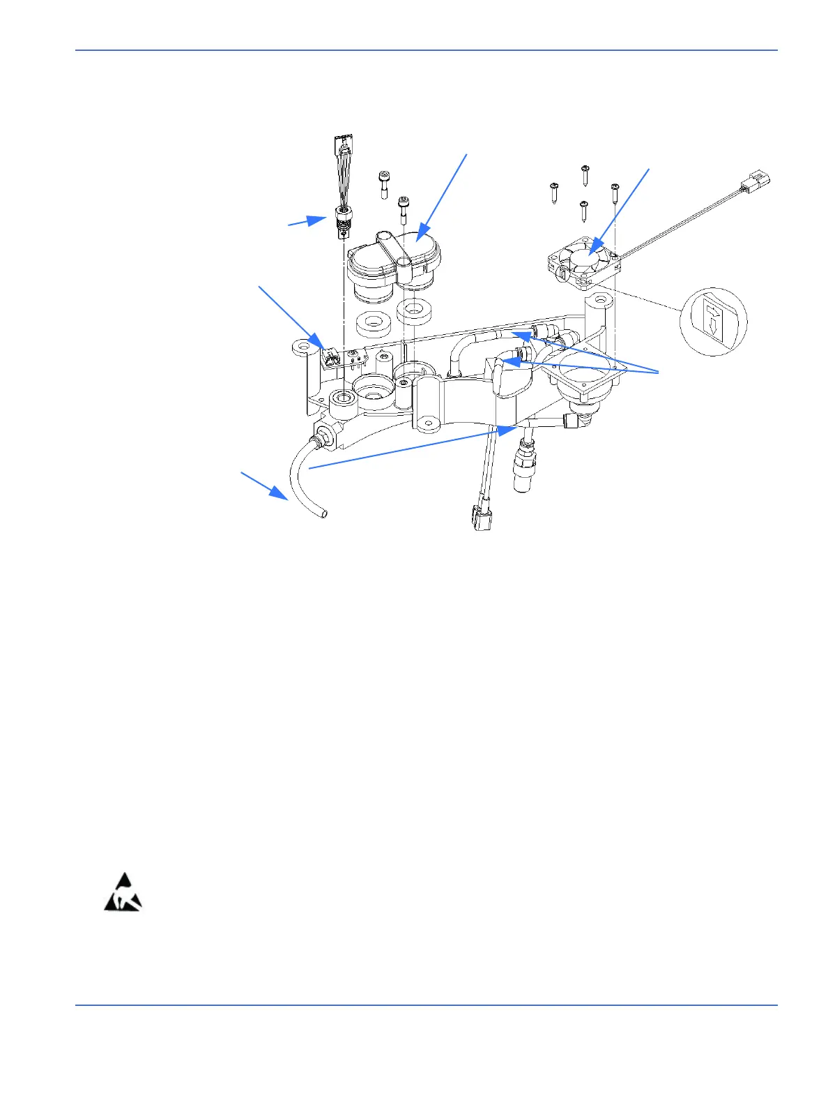
FIGURE 7-55. Sensor Housing
Sensor housing cover
Sensor plug assembly
PC board
White hoses
Calibration fan
Black hoses

 Loading...


