Chapter 7: Repair Procedures
Lower Device Repairs
7-46 Service Manual
7.9.2 Incubator Fan, Fan Motor, and Optical Fan Sensor
Refer to “Figure 7-48 Bed Disassembly”, “Figure 7-47 Heat Sink and Fan”, and “Figure 7-46 Fan Motor”.
1. Remove the rotating bed, translation deck, tilt platform, and pan.
2. Remove the fan, fan hub, and fan seal from the top of the fan motor shaft.
3. Remove the chassis cover. (Refer to “Removing the Chassis Cover with the Storage Drawer in Place” on
page 7-45.)
4. Disconnect the motor leads.
5. Remove the 4 screws in the motor bracket and remove the fan motor assembly.
6. The motor isolators pop out of the holes in the bracket.
7. To replace the optical sensor, disconnect its connector, remove the screw from the boss in the chassis
that holds it in place, and remove the assembly.
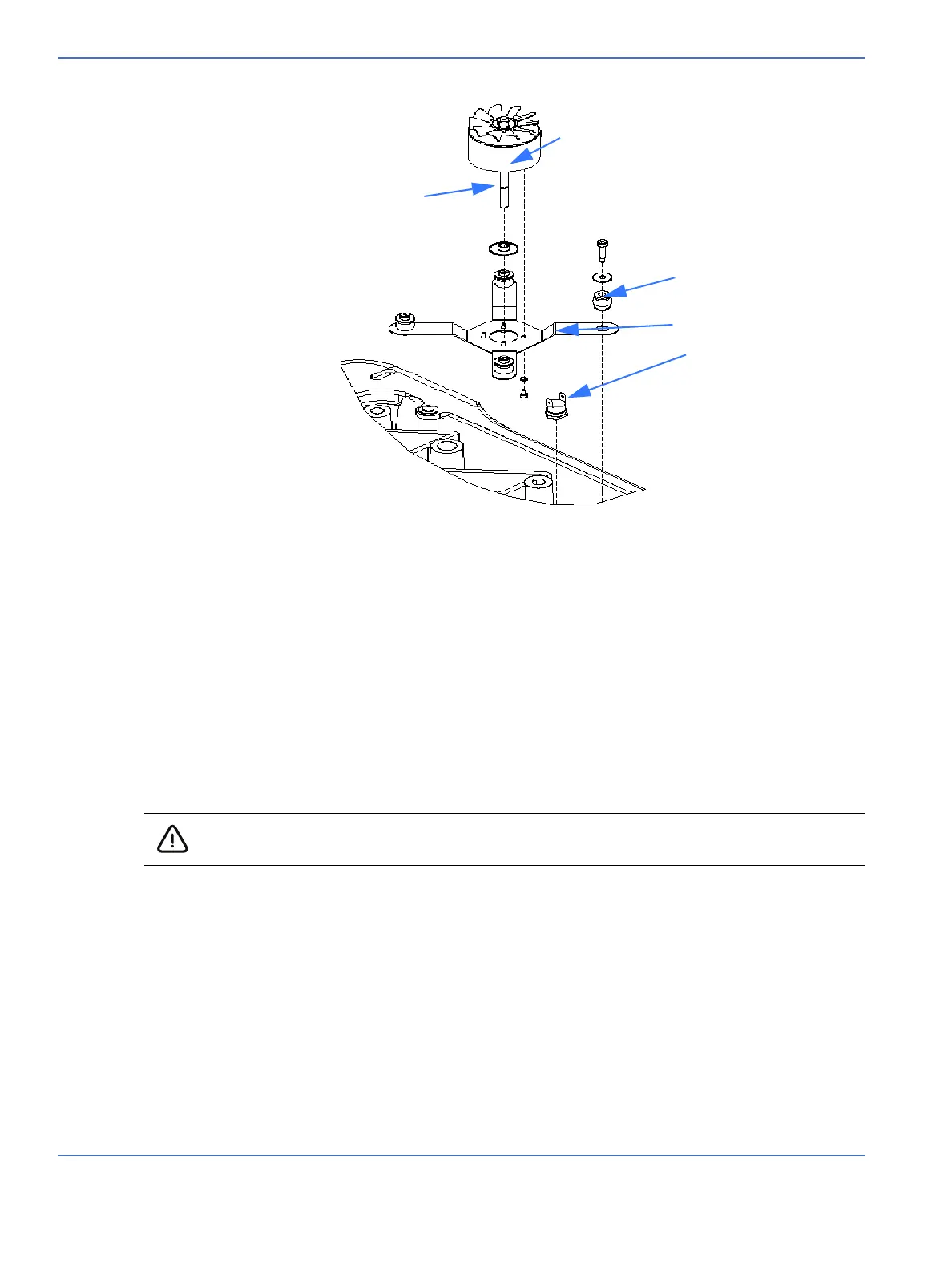
Motor
FIGURE 7-46. Fan Motor
Motor shaft
Motor isolators
Thermostat
Motor bracket
Caution: To avoid damaging a harness, make sure you do not pull the harness by the cable
wires. Instead, use the connector body to disengage or to engage the connectors.

 Loading...


