Chapter 7: Repair Procedures
Bed Tilt Brake Pad Replacement
7-52 Service Manual
11. Connect the blue and black connectors. Secure the connection using the plastic adhesive connector
locking pieces that you saved in step 6 or a new one (part number 6600-0572-600).
12. Tuck the connector assembly down between the chassis and the electronics enclosure.
13. Remove the adhesive backing on the new membrane switch and attach it to the chassis.
14. Replace the probe panel housing in its correct position.
15. Replace the two screws holding the probe panel housing to the electronics enclosure.
16. Replace the electronics enclosure cover.
17. Perform the post-service checkout including electrical safety.
7.10 Bed Tilt Brake Pad Replacement
Refer to “Figure 7-48 Bed Disassembly” and “Figure 7-50 Replacing the Tilt Brake Pad”.
1. Remove the mattress, clear plate, rotating bed and translation deck.
2. To release the tilt screw ball, squeeze the tilt mechanism and slide open the finger pocket latch until you
hear the ball drop.
3. Release the tilt platform from the chassis by pushing the pivot pin tabs in on both sides, then lifting the
tilt platform out of the chassis.
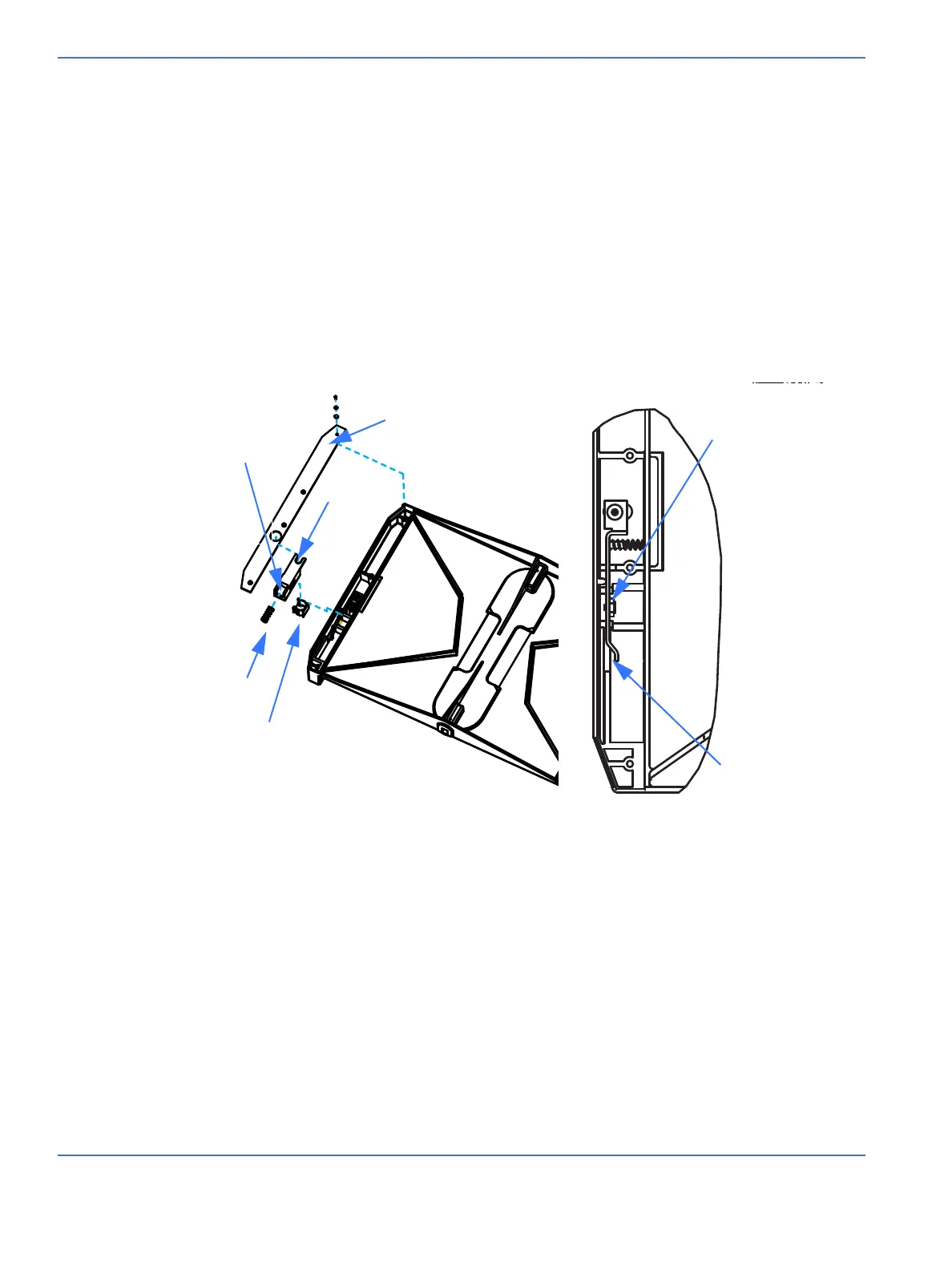
4. Turn the tilt platform over and remove the 4 screws (2.5 mm hex key) that secure the tilt assembly cover.
5. Remove the two plastic inserts. The long insert holds a positioning spring and the smaller ball insert
holds the screw ball in position.
6. Press back the brake lever to provide access to the tilt brake pad, then use pliers or a thin 14 mm open
end wrench to remove the nut to which the brake pad is fastened. Replace the tilt brake pad assembly
and reassemble.
FIGURE 7-50. Replacing the Tilt Brake Pad
Finger pocket latch
Positioning spring
Ball insert
Tilt platform
Long insert
Tilt assembly cover
Tilt brake pad
Brake lever
 Loading...


