Chapter 5: Troubleshooting
Additional Troubleshooting Tips
Service Manual 5-11
The 5V and 12V supplies are generated by the Power Supply and are sent to the Relay Board for
distribution.The +5STBY is generated on the Relay Board from either the 12V (normal operation) or the 8.4V
NiMH PF Battery (power fail). These 3 voltages are distributed to the other boards via various cables.
The easiest place to measure a power supply voltage is at one of the spare 4 pin connectors on the
Expansion Slot Power Bus.
5.2.5 Troubleshooting Harness Cables 6600-0701-700 and 2075837-001
If DC power wire harness (6600-0701-700) or power supply DC output harness (2075837-001) is
disconnected or damaged, perform the following steps.
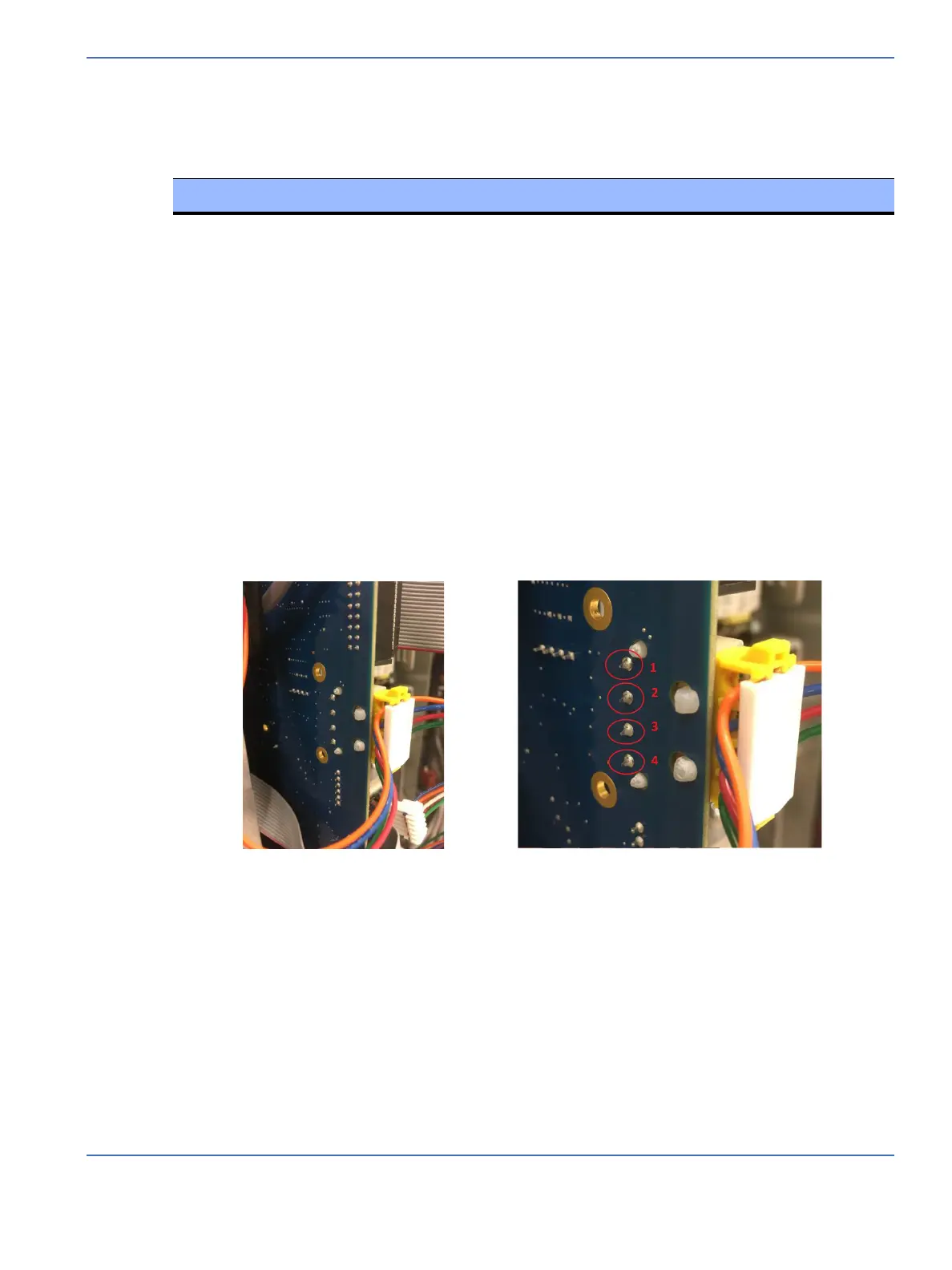
1. Open the electronics enclosure on the back of the incubator and pull the control board out until you
expose the power connector (it is the 4-wire cable in the middle of the control board). See Figure 5-6.
FIGURE 5-6. Exposing the Power Connector
2. Use a digital multimeter to measure the voltages between pin 1 and pins 2, 3 and 4, respectively.
Note: Pin 1 is ground and is the top-most pin.
a. Connect the negative (com) probe of multimeter to pin 1 and the positive probe to pin 2. The
voltage shall be more than 4.75V. If not, either harness 6600-0701-700 or harness 2075837-001 is
defective. Order new harnesses and replace them both.
b. Connect the negative (com) probe of multimeter to pin 1 and the positive probe to pin 3. The
voltage shall be more than 11.5V. If not, either harness 6600-0701-700 or harness 2075837-001 is
defective. Order new harnesses and replace them both.
Board Cable
Control Board Expansion Slot Power Bus (6600-0701-700) from Relay Board
Servo Oxygen Board Expansion Slot Power Bus (6600-0701-700) from Relay Board
RS-232 Board RS-232 Cable (2074735-001) from Control Board
ICSBC Rail Power Cable (6600-0706-700) from Expansion Slot Power Bus
Alarm Board LINCAN Cable (2069666-001) from ICSBC

 Loading...


