Chapter 5: Troubleshooting
Switches/Thermostat
5-12 Service Manual
c. Connect the negative (com) probe of multimeter to pin 1 and the positive probe to pin 4. The
voltage shall be more than 4.75V. If not, harness 6600-0701-700 is defective. Order a new harness
and replace it.
Note: When replacing either harness, do not to pull by the cable wires, but use the connector body to
disengage or engage connectors.
Note:
If the voltages on pins 2, 3, 4 are all within the acceptable voltage range, then both harnesses are
good to use and the symptom is not related to harness damage.
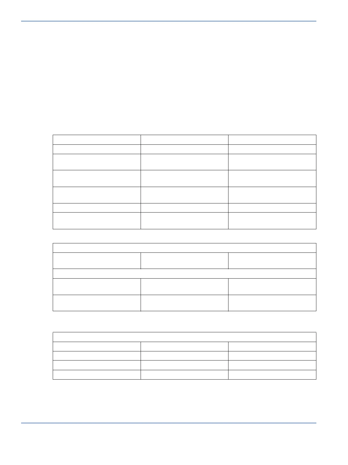
5.3 Switches/Thermostat
Use switch status diagram on the Switches service screen to assist in troubleshooting the switches.
When closed the resistance should be less than 200 ohms.
Canopy up detect Relay bd J36 pins 1-2 Closed when canopy is up
Canopy down detect Relay bd J36 pins 7-8 Closed when canopy is down
Canopy middle Relay bd J36 pins 4-5 Closed momentarily during
transition
Heater doors open Relay bd J31 pins 2-3 Closed when both heater doors
are open
Heater doors closed Relay bd J31 pins 1-3 Closed when both heater doors
are closed
Humidity reservoir Relay bd J32 pins 2-3 Closed when reservoir is closed
Add water thermostat Relay bd J32 pins 1-3 Opens when reservoir needs
water
Canopy foot control
Left or Right Relay bd J40 pins 3-4 Closed when either switch is
pressed
Elevating Base Foot Control
Left or right up Relay bd J40 pins 2-4 Closed when either switch is
pressed
Left or right down Relay bd J40 pins 1-4 Closed when either switch is
pressed
Canopy hand control
Left up Relay bd J35 pins 2-4 Closed when switch is pressed
Left down Relay bd J35 pins 3-4 Closed when switch is pressed
Right up Relay bd J35 pins 6-5 Closed when switch is pressed
Right down Relay bd J35 pins 7-5 Closed when switch is pressed

 Loading...


