Chapter 8: Illustrated Parts
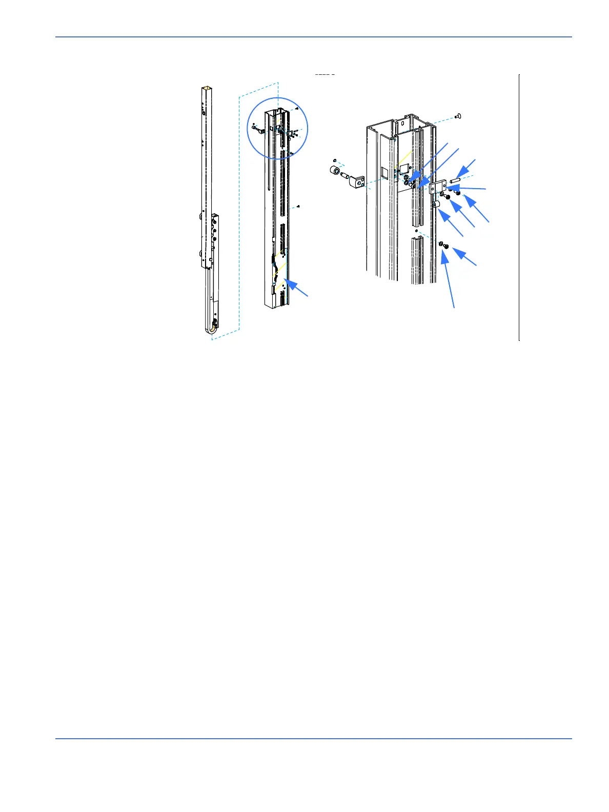
Uprights and Lift Rail Components
Service Manual 8-43
1. Spring, upper*....................................................................................6600-1464-500
2. Spring, lower*.....................................................................................6600-1465-500
3. Spring, left (west) only* ..................................................................6600-1725-500
4. Screw, M5 x 20 socket head........................................................6600-1152-400
5. Spacer....................................................................................................6600-1103-400
6. Roll pin ...................................................................................................6600-1093-400
7. Stop block, left (west) only............................................................6600-1712-500
8. Heater wire harness/cable carrier assembly*** ...............6600-0710-700
9. Spring bracket, left (west) only...................................................6600-1350-500
10. Spring spool ....................................................................................6600-1317-500
11. Plastic washer .................................................................................6600-1708-500
12. Lift rail..................................................................................................6600-1333-500
13. Screw, M4 x 12 flat head socket .............................................6600-0708-409
14. Split ring lock washer, M5...........................................................6600-0713-404
15. Screw, M5 x 10 button head socket......................................6600-0706-417
16. Side roller pin**...............................................................................6600-1098-400
17. Side roller bracket** .....................................................................6600-1451-500
18. Screw, M4 x 10 socket head......................................................6600-0707-409
19. Split ring lock washer M4...........................................................6600-0713-403
20. Side roller**.......................................................................................6600-1450-500
21. Screw, M4 x 8 socket head ........................................................6600-0707-408
22. Star washer M4 Int........................................................................6600-0713-432
23. Retaining ring ..................................................................................6600-1182-400
24. Front roller.........................................................................................6600-1770-500
25. Front roller pin.................................................................................6600-1496-500
26. Front roller bracket .......................................................................6600-1483-500
27. Left (west) upright..........................................................................6600-1204-500
28. Ground Harness ...........................................................................6600-0883-700
29. Rivet .................................................................................................6600-1160-400
30. Snap Bushing ..............................................................................6600-0037-500
31. Cable Tie ......................................................................................6600-0384-400
*Replace all the buoyancy springs at one time.
STEP 7
STEP 7
27
23
24
25
26
13
14
15
16
17
18
19
20
21, 22, 28, 22
21, 22, 28, 22

 Loading...


