Niro Soavi S.p.A
FIGURE 4.10.1
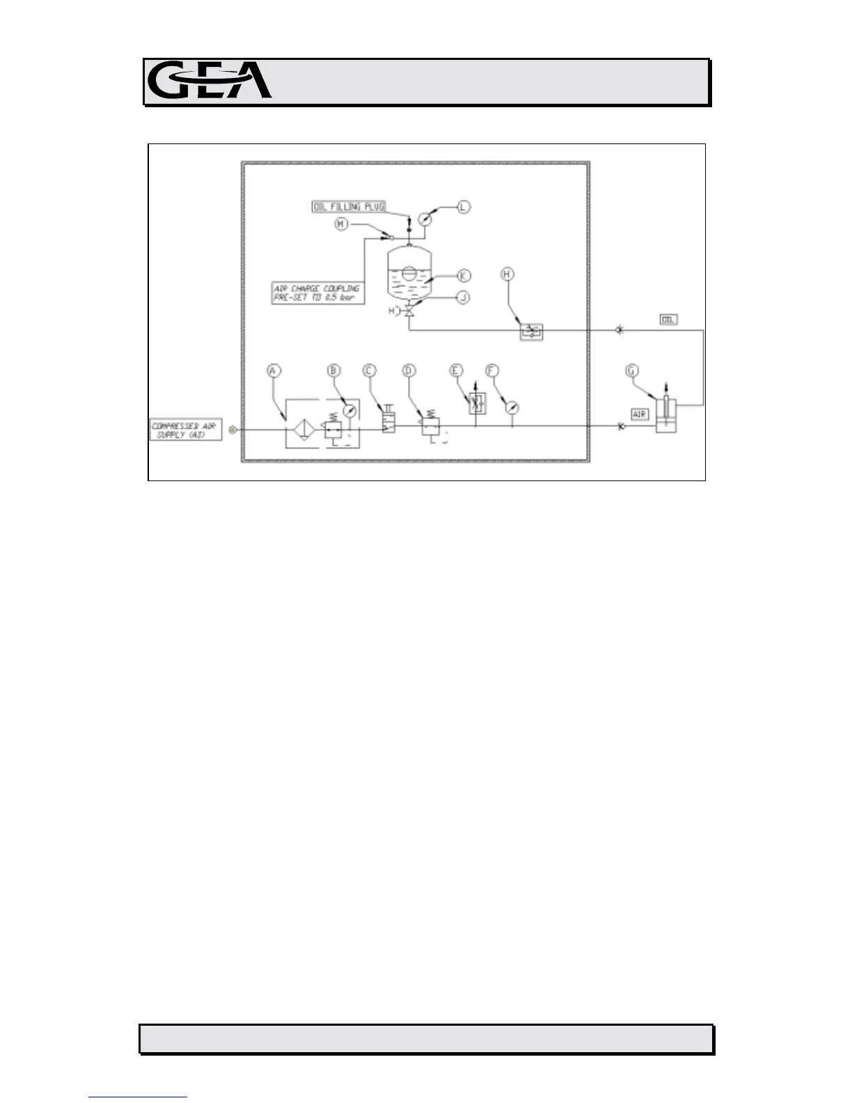
The components present on the circuit accordino to the scheme presented in
figure 4.10.1 are:
- Inlet air pre-treatment unit (A) with pressure gauge (B)
- One pneumatic switch (C) (or as option a solenoid valve) to give pressure to
the actuator (G)
- One manual pressure regulator (D) (or as option a proportional valve for
remote controls
- Throttle valves (E, H) to achieve a stable operation of the pneumatic system
and to adjust the speed of the raise of the homogenizing pressure by
throttling the oil backflow
- A pressure gauge (F) installed on the machine front panel, indicating the
pressure effectively supplied to the pneumatic actuator
- A damper tank (K) for oil and pressurized air
The effect of dampening of the vibrations induced on the homogenizing valve by
the normal reciprocating movement of the plungers is granted by a suitable
air/oil damper vessel (K) which is connected to the lower part of the pneumatic
actuator of the homogenizing group.
This damper tank is preloaded with compressed air, pressure 0,5 bar.
The gauge (L) allows to check the pressure in the tank, and ina case of need it
is possibile to use the quick connection (M) to restore the correct pressure
inside the tank.
If the pneumatic dampening system is checked on a regular basis for correct
preload pressure and oil level, it is possible to avoid problems of valve
4c101e0c.doc 4.10.2