VLT
®
5000 Series
VAR 2
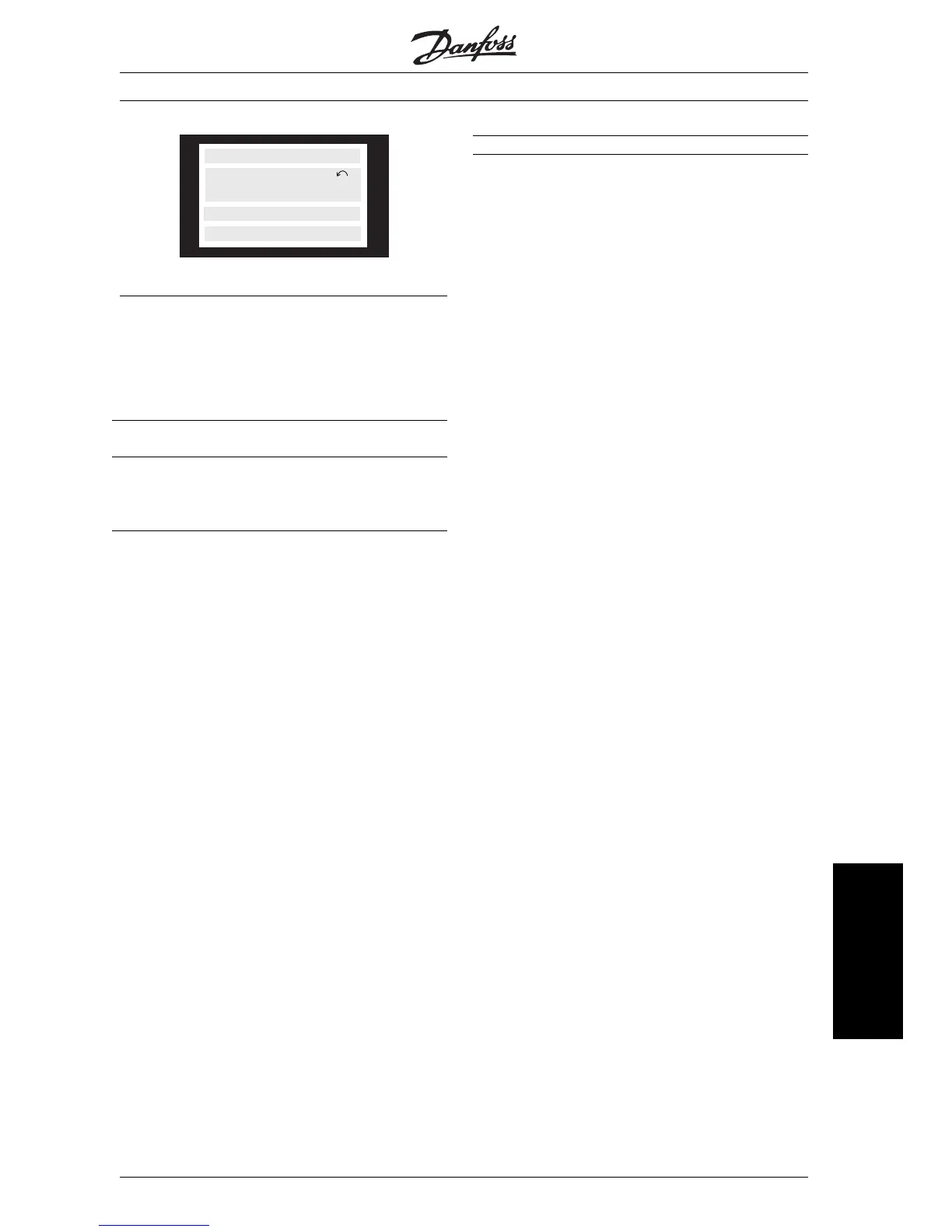
SETUP
1
STATUS
VAR 1.1 VAR 1.2 VAR 1.3
■ Display mode - selection of read-outstate
There are three options in connection with the
choice of read-out state in the Display mode - I, II
and III. The choice of read-out state determines the
number of operating variables read out.
Read-out
state:
I: II: III:
Line 1 Description for
operating vari-
able in line 2
Data value for
3 operating
variables in
line 1
Description for
3 operating
variables in
line 1
The table below gives the units linked to the vari-
ables in the first and second line of the display.
Operating variable: Unit:
Reference [%]
Reference [unit]
Feedback [unit]
Frequency [Hz]
Frequency x scaling [-]
Motor current [A]
Torque [%]
Power [kW]
Power [HP]
Output energy [kWh]
Motor voltage [V]
DC-link voltage [V]
Motor thermal load [%]
VLT thermal load [%]
Hours run [Hours]
Input status, dig. Input [Binary code]
Input status, analogue terminal 53 [V]
Input status, analogue terminal 54 [V]
Input status, analogue terminal 60 [mA]
Pulse reference [Hz]
External reference [%]
Status word [Hex]
Brake effect/2 min. [kW]
Brake effect/sec. [kW]
Heat sink temp. [ºC]
Alarm word [Hex]
Control word [Hex]
Warning word 1 [Hex]
Extended status word [Hex]
Communication option card warning [Hex]
RPM [min
-1
]
RPM x scaling [ - ]
Operating variables 1.1 and 1.2 and 1.3 in the first
line, and operating variable 2 in the second line are
selected via parameter 009, 010, 011 and 012.
MG.51.A1.02 - VLT is a registered Danfoss trade mark
73
Operation of the VLT
frequency converter








 To Next Page