VLT
®
5000 Series
3. The values are obtained by means of manual
measurements:
-R
S
can be calculated by measuring the resis-
tance R
PHASE-to-PHASE
between two phase
terminals. If R
PHASE-to-PHASE
is lower than 1-2
ohm (typically motors >4-5.5 kW, 400 V), a spe-
cial ohm-meter should be used (Thomson bridge
or similar). R
S
= 0.5 x R
PHASE-to-PHASE
4. The factory settings of R
S
, selected by the VLT
frequency converter itself on the basis of the mo-
tor nameplate data, are used.
NB!:
If the setting in parameter 102-109 is
changed, the parameters 110-118 will return
to factory setting.
109
109 Stator reactance
(STATOR REACT.)
Value:
✭depends on the choice of motor
Function:
After setting motor data in parameters 102-106, a
number of adjustments of various parameters are
made automatically, including the stator resistance
X
S
. The shaft performance can be improved by fine-
tuning R
S
and X
S
, see procedure below.
Description of choice:
X
S
can be set as follows:
1. Automatic motor adaptation, where the VLT fre-
quency converter measures on the motor to
determine the value. All compensations are reset
to 100%.
2. The values are stated by the motor supplier.
3. These values are obtained by means of manual
measurements:
-X
S
can be calculated by connecting a motor to
mains and measuring the phase-to-phase voltage
U
L
as well as the idling current I .
Alternatively , these values can be recorded dur-
ing operation in idle running state at the rated
motor frequency f
M,N
, slip compensation (par.
115) = 0% and load compensation at high speed
(par. 114) = 100%.
X
S
=
U
L
p
3
xl
8
4. The factory settings of X
S
, selected by the VLT
frequency converter itself on the basis of the mo-
tor nameplate data, are used.
NB!:
If the setting in parameter 102-109 is
changed, the parameters 110-118 will return
to factory setting.
110
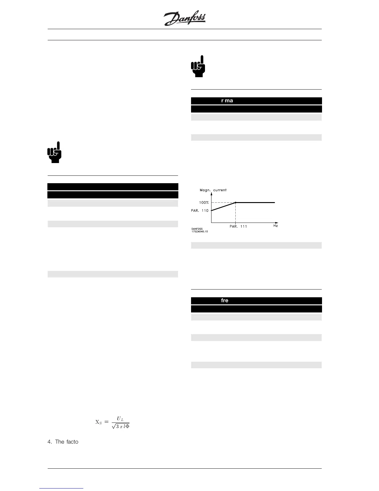
110 Motor magnetizing, 0 rpm
(MOT. MAGNETIZING)
Value:
0 - 300 %
✭ 100 %
Function:
This parameter can be used if a different thermal
load on the motor is desired when running at low
speed.
This parameter is used in connection with parameter
111.
Description of choice:
Enter a value stated as a percentage of the rated
magnetizing current.
Too low setting may lead to a reduced torque on the
motor shaft.
111
111 Min. frequency normal magnetizing
(MIN FR NORM MAGN)
Value:
0.1 - 10.0 Hz
✭ 1.0 Hz
Function:
This parameter is used in connection with parameter
110. See drawing in parameter 110.
Description of choice:
Set the required frequency (for normal magnetizing
current). If the frequency is set lower than the motor
✭
= factory setting. () = display text [] = value for use in communication via serial communication port
MG.51.A1.02 - VLT is a registered Danfoss trade mark
114
 Loading...