Niro Soavi S.p.A
4C042E0C.DOC 4.4.12
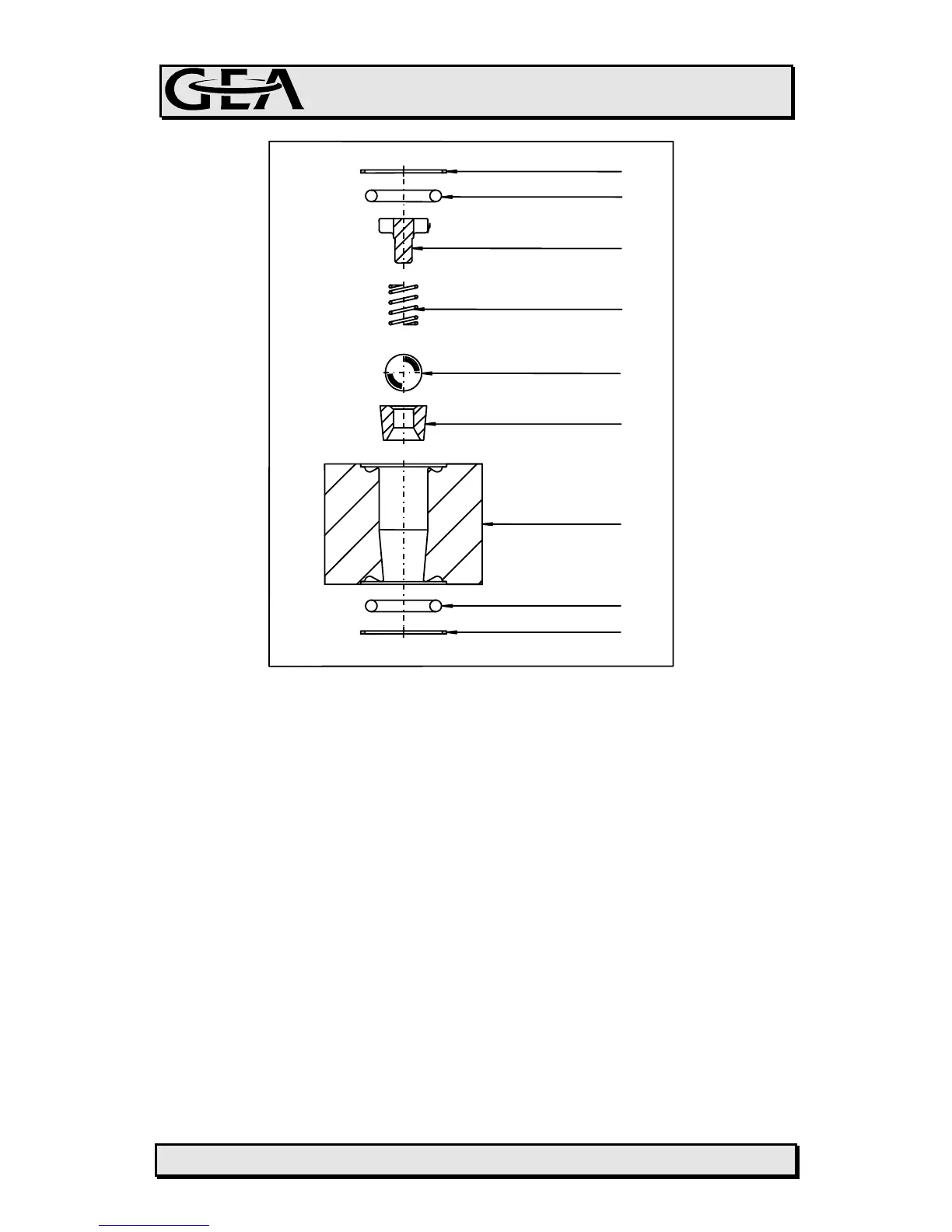
FIGURE 4.4.6
4.4.3.2 ASSEMBLING
To mount the valve assemblies refer to figures 4.4.5 and 4.4.6 (as an
alternative).
• Carefully place the o-rings (H + N + F) and the relative anti-extrusion rings (L
+ P + G) in the slots provided, if necessary use food-grade vaseline to hold
them in position
• For delivery valve assemblies, position the seat housing (A), and the guide
(M) where present, using the existing studs as guides
• For suction valve assemblies, the seat housing (A), and the guide (M) where
present, must be placed on the bottom support flanges or on the suction
manifold itself, if made as one single element (depending on machine model)
• Insert the inner components: ball (D), spring (C) and valve cap (B), making
sure that the position of the spring is correct
• If necessary check that the ball (D) can be lifted, by pushing it from
underneath
L
H
A
P
N
B
C
D
E