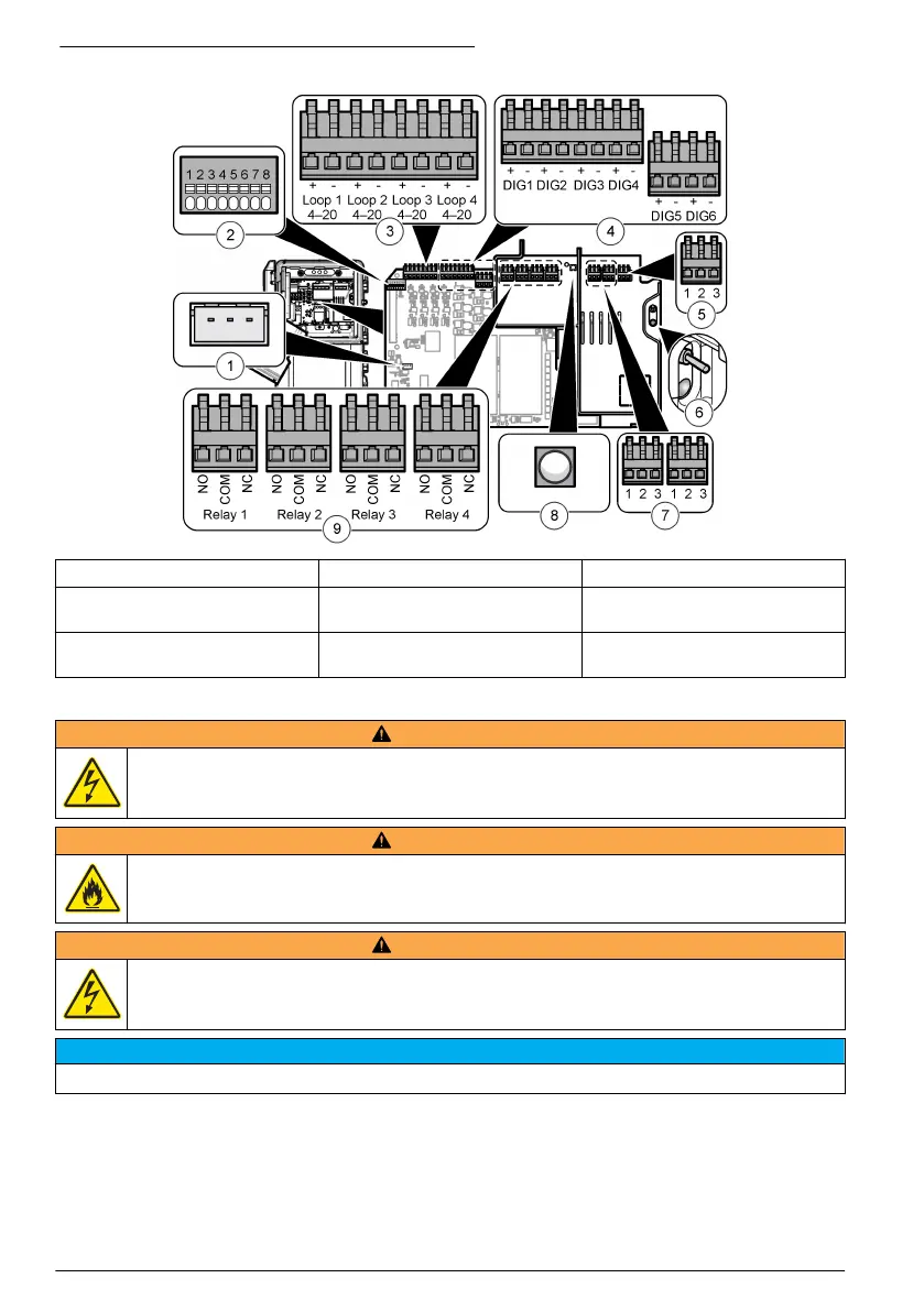
Figure 12 Connections on the main circuit board
1 External controller connection 4 Digital inputs 7 Power out
2 Smart probe connection 5 Power in 8 Power out LED (on = power is
connected to the analyzer)
3 4–20 mA outputs 6 Power switch and LED (on =
analyzer is on)
9 Relays
Connect to power
W A R N I N G
Electrocution hazard. Use a crimp‐on ring terminal on the main protective earth connection.
W A R N I N G
Electrical shock and fire hazards. Make sure that the user-supplied power cord and non‐locking plug
meet the applicable country code requirements.
W A R N I N G
Electrocution hazard. Make sure that the protective earth conductor has a low impedance connection of
less than 0.1 ohm. The connected wire conductor must have the same current rating as the AC mains
line conductor.
N O T I C E
The instrument is used for a single phase connection only.
Cord installation: The manufacturer recommends to use the optional cord and sealing gland. Refer
to the maintenance manual for the replacement parts list. For a customer-supplied cord, three
1.0 mm
2
(18 AWG) conductors are required with a waterproof outer jacket, and the cord must be
shorter than 3 meters (10 feet). Use a sealing type strain relief to keep the environmental rating of
the instrument. Refer to Specifications on page 21. To connect power to the instrument, refer to
Table 1 or Table 2 and Figure 13.
14
English

 Loading...