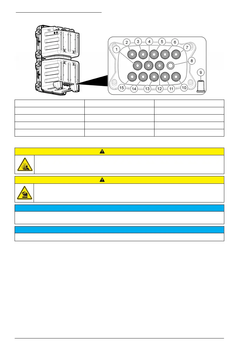
Figure 5 Ports for six sample streams
1 Sample 6 bypass drain 6 Sample 2 bypass drain 11 Sample 2 inlet
2 Sample 5 bypass drain 7 Sample 1 bypass drain 12 Air purge inlet (optional)
3 Sample 4 bypass drain 8 Chemical drain 13 Sample 3 inlet
4 Sample 6 inlet 9 Case drain for spills or leaks 14 Sample 4 inlet
5 Sample 3 bypass drain 10 Sample 1 inlet 15 Sample 5 inlet
Plumb the sample and drain lines
C A U T I O N
Explosion hazard. Use only the supplied regulator from the manufacturer.
C A U T I O N
Chemical exposure hazard. Dispose of chemicals and wastes in accordance with local, regional and
national regulations.
N O T I C E
Do not connect the drain lines to other lines or backpressure and damage to the analyzer can occur. Make sure
that the drain lines are open to air.
N O T I C E
The pressure regulator is set to a fixed pressure and cannot be changed.
Use the supplied tubing (6 mm), Y-strainer with filter and pressure regulator to plumb the drain and
the sample to the analyzer. Refer to Figure 6. The sample line tubing that goes into the plumbing
access ports must be 6 mm. Tubing of 1/4 in. may be used for the sample line up to the valve/y-
strainer but not into the plumbing access ports of the analyzer.
8
English

 Loading...