39
!
"
#
$
%
&
!
"
#
$
%
&
!
"
#
Saw-Spindle Moulder
B3 / B3 e-classic
Making adjustments and preparations
8.3 Crosscut fence on the sliding table
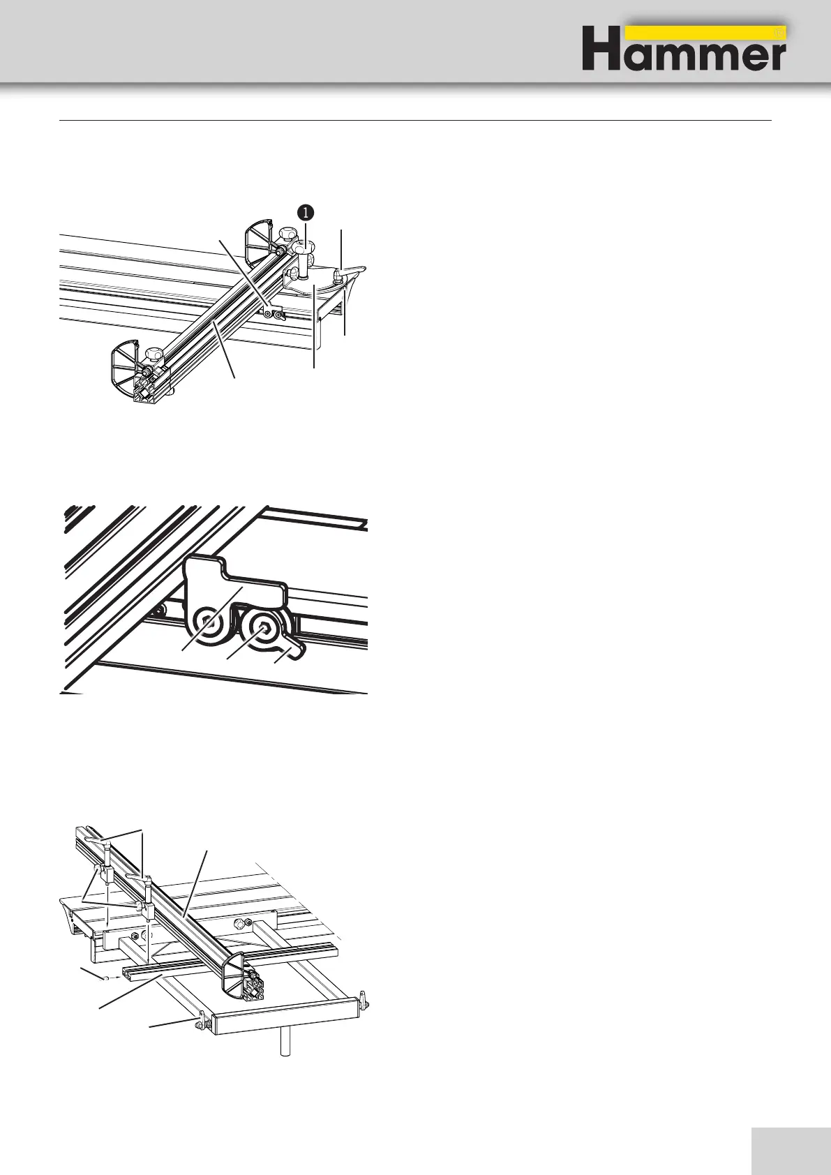
Fig. 8-2: Assembling the crosscut fence
1. Thread the clamping device of the crosscut fence into
the groove of the sliding table and move it right up to
the stop screw (in the groove).
2. Loosely affix the compressor rod shaft.
3. Adjust the desired cutting angle (-45° to +45°).
With 90° cuts:
• Flip open the end stop on the sliding table.
• Place the fence against the end stop.
4. Clamp the stop with the clamping lever.
! Compressor rod shaft $Clamping device
" Single-hand clamp lever %End stop
# Groove &Stop
Fig. 8-3: Adjusting the end stop
Adjusting:
1. Fold the end stop back.
2. Loosen the setscrew.
3. Turn the cam lever until a 90° angle is attained (the
fence reaches the end stop).
4. Check with a sample cut.
5. Tighten the setscrew.
! End stop
" Setscrew
# Cam lever
8.4 Crosscut fence on the outrigger
Fig. 8-4: Assembling the crosscut fence
The crosscut fence can be mounted onto the outrigger on
the push side.
1. Thread the locking plate into the outrigger rail.
2. Loosen the thumb screws and position the crosscut
fence at the outrigger.
3. Clamp the crosscut fence at the outrigger with the
clamping lever.
4. Tighten the thumb screws.
! Clamping lever $Outrigger
" Crosscut fence %Locking plate
# End stop &Thumb screws