64
1
2
3
4
5
6
7
8
9
100 125 150 175 200 225 250 275 300
nmax (x 1000)
ø 25 / 25,4 mm
10
20
30
50
80
100
mm
ø mm
1
2
3
4
5
6
7
8
100 125 150 175 200 225 250 275 300
9
ø 30 / 35 mm
ø 31,75 mm
10
20
30
50
80
100
mm
ø mm
n
max (x 1000)
2
3
4
5
6
7
8
9
100 125 150 175 200 225 250 275 300
ø 40 mm
10
20
30
50
80
100
mm
nmax (x 1000)
ø mm
2
3
4
5
6
7
8
9
100 125 150 175 200 225 250 275 300
ø 50 mm
30
50
80
100
mm
n
max (x 1000)
ø mm
Saw-Spindle Moulder
B3 / B3 e-classic
Making adjustments and preparations
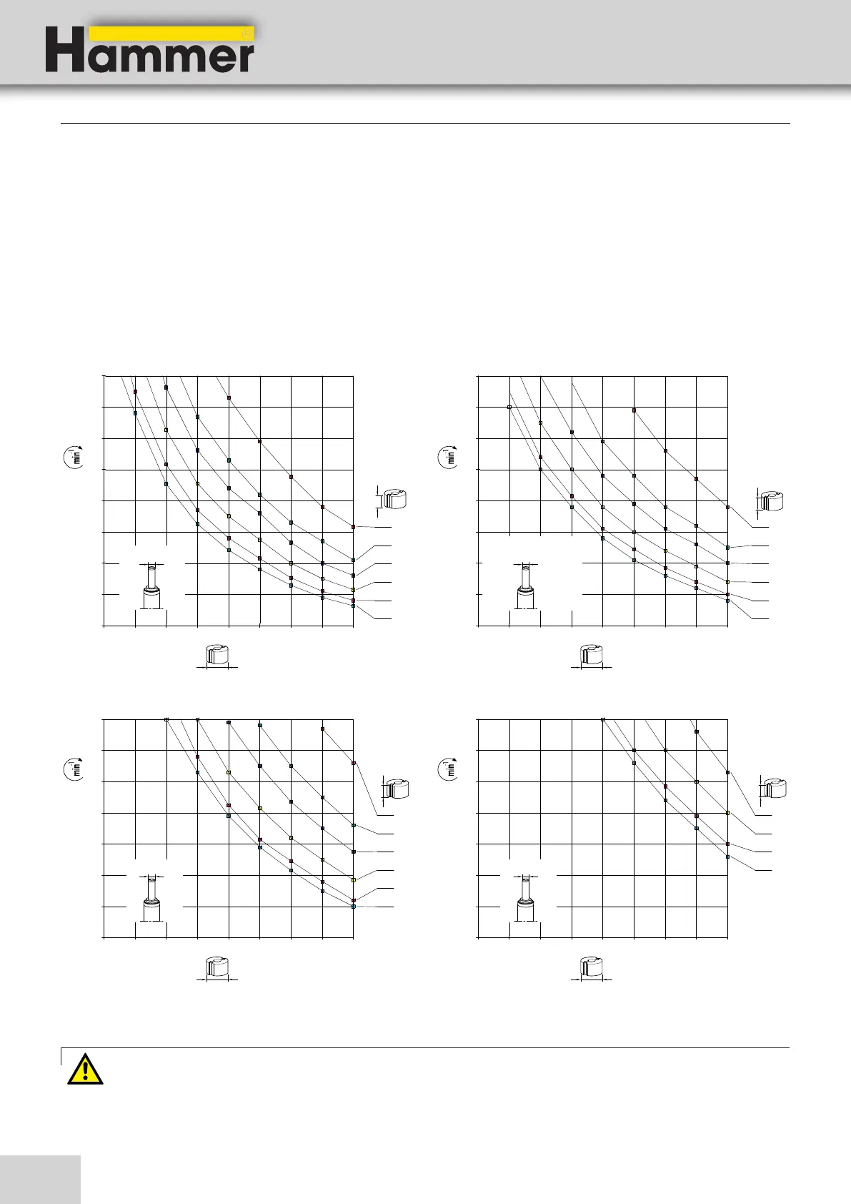
9.8.2 Maximum spindle resiliance (rotation limit)
1. Calculate minium rotation speed (boundary value) depending on the tool diameter and length of cut using this
diagram.
2. Using the sticker on the chassis cover, set the correct spindle rotation on the machine.
3. Set the obtained spindle speed.
Fig. 9-20: Diagrams - Maximum spindle load
Warning! Risk of injury! / Risk of material damage!
Do not exceed the limit value obtained from the diagram!