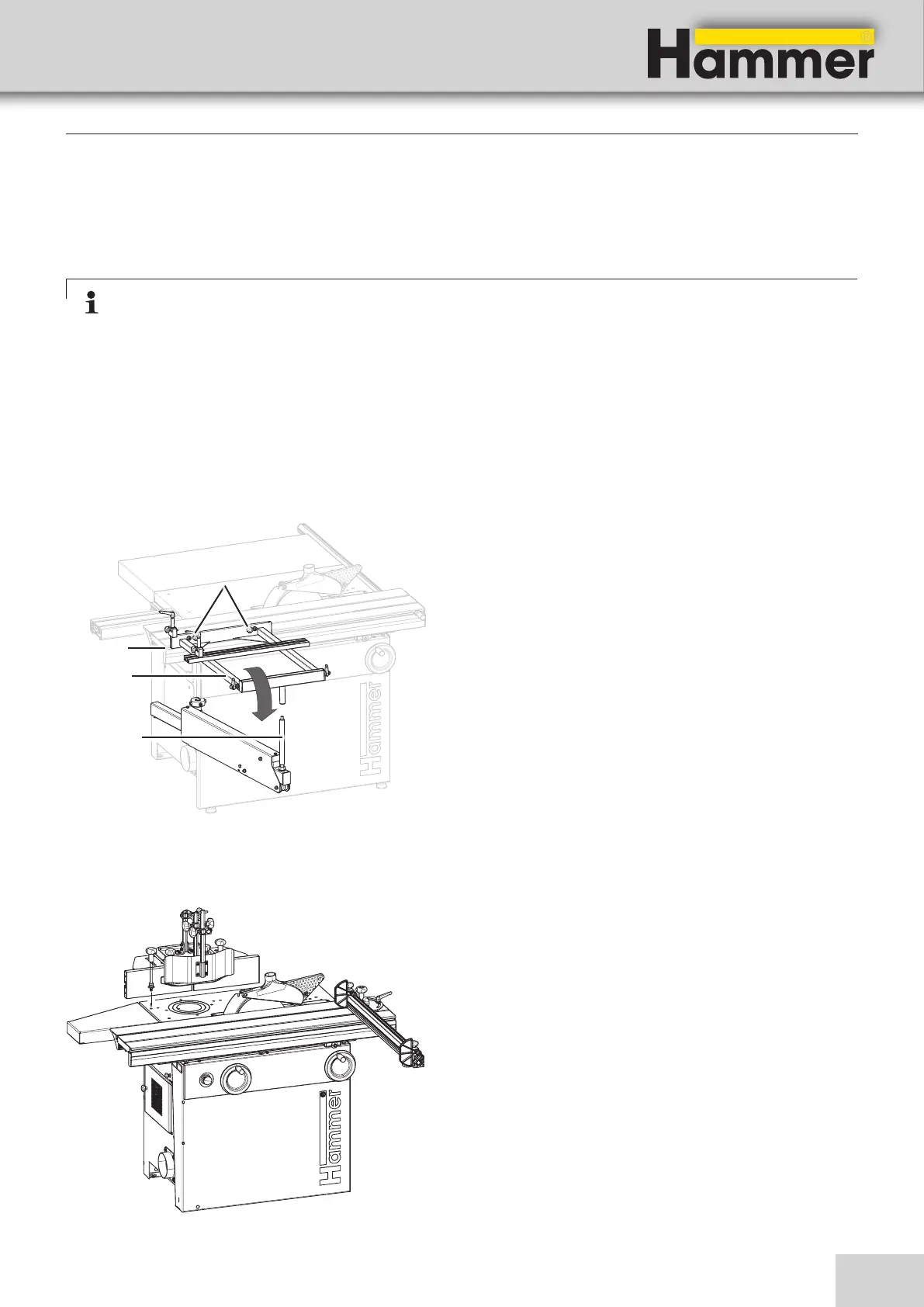
35
!
"
#
$
Saw-Spindle Moulder
B3 / B3 e-classic
Fig. 7-6: Spindle moulder fence
The spindle moulder fence is completely assembled upon
delivery and is mounted to the machine.
If transported in a container, the spindle moulder fence is
mounted and delivered separately from the pallet. In this
case, the spindle moulder fence has to be placed onto
the machine and fastened securely.
7.4.3 Spindle moulder fence
7.4 Assembly
7.4.1 Sliding table
Attention: Due to transport reasons, the sliding table, depending on its length, may be packaged
separately. Two to three additional helpers, depending on the cutting length, are required to install the
machine.
The sliding table has to be set up before the initial machi-
ne start-up. Individual installation instructions are found
with the machine or the sliding table.
Setup and installation
7.4.2 Assembling/disassembling the outrigger table
Fig. 7-5: Assembling the outrigger table
Assembling the outrigger table:
1. Hook the outrigger table into the groove on the
sliding table.
2. Place the outrigger table onto the support arbor.
3. Fix with a thumb screw.
Disassembling the outrigger table:
1. Loosen the thumb screw.
2. Unhook the outrigger table from the support arbor
and the sliding table.
!Groove
"Outrigger table
#Support arbor
$Thumb screws