89
!
&
/
*
)
BL
%
BM
BN
BO
BP
BQ
BR
!
"
#
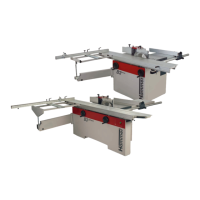
Saw-Spindle Moulder
B3 / B3 e-classic
Fig. 12-12: Base
On the base:
8. Screw the flat head screws in.
9. Screw in the socket head cap screws with washers.
10. Screw the base cover on with fillister head screws.
& Washers
/ Socket head cap screws
* Fillister head screws
) Base cover
BL Flat head screws
On the opposite side on the sliding table:
11. Screw the bearing shaft on with flat head screw and
hexagon nut.
12. Screw the flat head screws in.
13. Screw the sliding table cover on with fillister head
screws.
BM Sliding table cover
BN Bearing shaft
BO Hexagon nut
BP Flat-head screw
BQ Flat head screws
BR Fillister head screws
Fig. 12-13: Sliding table
Maintenance
12.11 Lubricating the spindle moulder socket and tilting segments
Fig. 12-14: Spindle moulder socket
1. Switch the machine off and ensure that it cannot be
switched on again.
2. Move the spindle moulder right to the top and tilt to a
90° position.
3. Remove chips, dust and grease residues.
4. Lubricate the left and right tilting segments and the
spindle moulder socket with machine grease.
5. Move the spindle moulder, repeatedly, up and down.
6. Move the spindle moulder, repeatedly, between the
45° and 90° positions.
7. If required, lubricate again.
!Spindle moulder socket
"Right
#Left