57
#
!
"
!
"
#
$
Saw-Spindle Moulder
B3 / B3 e-classic
The spindle moulder guard unit is mounted on the moul-
ding fence. It consists of an adjustable linkage, the pres-
sure shoe and the pressure spring.
1. After releasing the thumb screws, the individual com-
ponents can be adjusted vertically and horizontally.
2. The vertical pressure shoe and the horizontal pressu-
re spring are adjusted in such a way so as to lightly
bias (pressure) the workpiece against the table and
respectively against the fence boards.
3. To change tools, open the thumb screws and open
the moulding fence cover with the installed spindle
moulder guard toward the back.
!Thumb screw $Pressure shoe
"Rod #Pressure spring
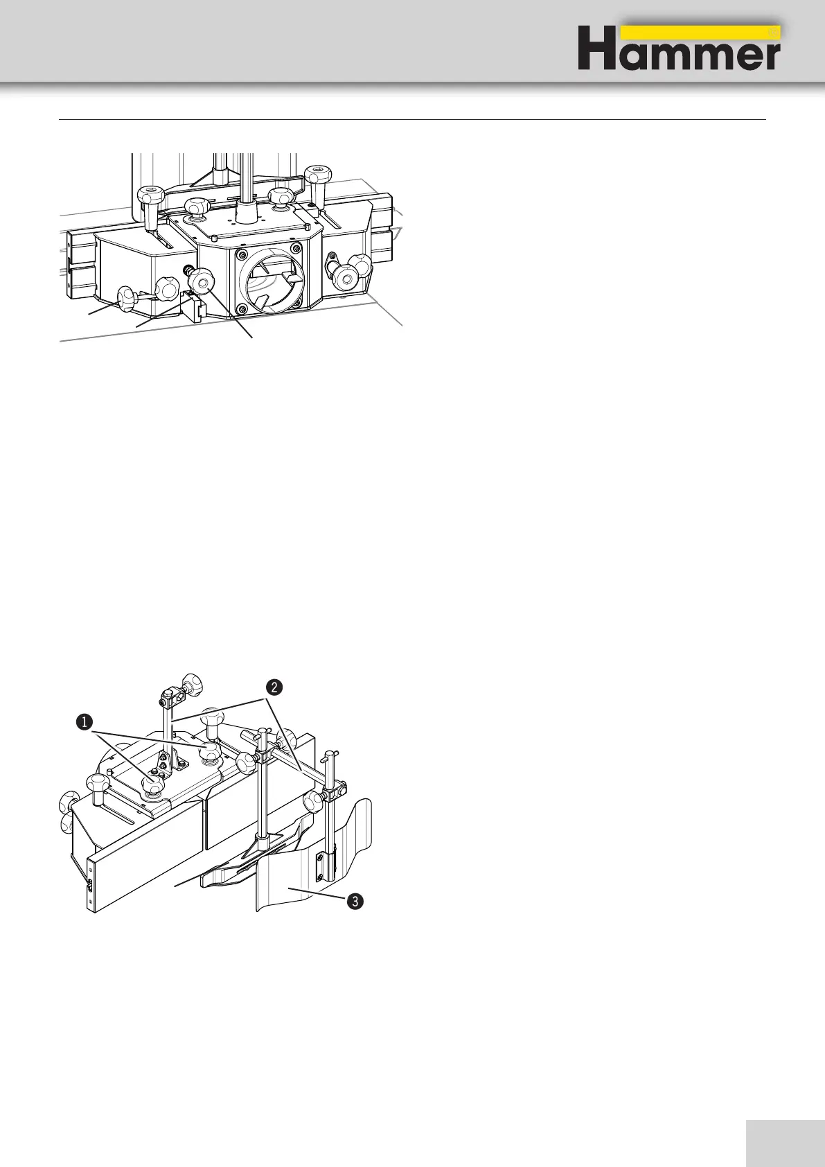
Fig. 9-5: Fine adjustment for outer tool diameter
2. After opening the outer tool diameter clamping
screw, adjust the shaper fence roughly in relation to
the outer tool diameter.
3. Tighten the outer tool diameter clamping screw.
4. Now you can fine adjust the entire shaper fence to
the outer tool diameter via the handwheel.
5. On scale, you can directly read the outer tool diame-
ter to which the rigid straightedge is set.
To ensure that the settings remain unchanged after re-
moving and remounting the shaper fence, you have to
compensate for play in the fitting bolt by always app-
lying light pressure backwards on the depthadjustable
straightedge when setting. After adjusting, tighten the
shaper fence to the machine table via the clamping bolts.
!Circle of cut clamp screw
"Scale
#Handwheel
9.4.3 Spindle moulder guard attachment
Fig. 9-6: Spindle moulder guard
Making adjustments and preparations