Chapter 7: Troubleshooting installation
Tools
• Standard AC voltmeter
• Standard DC voltmeter
1. Open the Ripple node lid.
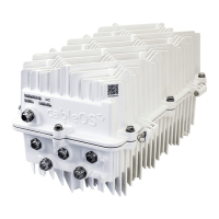
2. Observe and record the status (lit or not lit) of all LEDs on any component within the Ripple node.
Example: An unlit power-supply green LED (+34V or +24V) may indicate that the power supply is
faulty.
3. Measure and record the AC input voltage at the AC1 and/or AC2 test point(s) at each RF port.
See Checking the AC power level on the Ripple node.
If you are using AC power to the power supply modules, you can check the AC input voltage to the
node from the AC test point on the power supply module.
4. Measure and record the DC voltages at the DC test points on the power supply modules; if AC power
is available at the power supplies, measure and record the AC voltage at the AC test point on the
power supply modules.
Figure 7-1: Power supply LEDs and AC and DC power test points
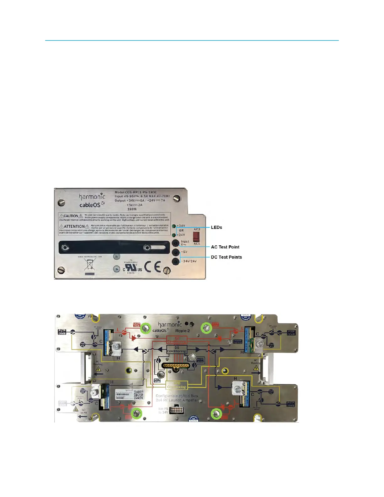
5. Measure and record the RF return-path output at each port at the internal RF test points on the RF
launch amplifier.
Figure 7-2: Internal return-path RF test points
104