Chapter 4: Installing the Ripple-2 Node
Warning: The outer conductor of the coaxial cables connected to the node must be grounded
according to safety regulations pertaining to equipotential bonding system. This grounding may
be performed either at the subscriber’s building, or at the node site.
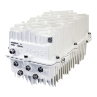
There are four RF output ports, two on each side of the node; they are labeled P1, P2, P3, P4. Coaxial
cables can be attached to any or all of these input ports, in any combination.
NOTE: Ports P5 and P6 are used for optional local channel insertion and dedicated port powering
features.
Figure 4-3: RF output ports
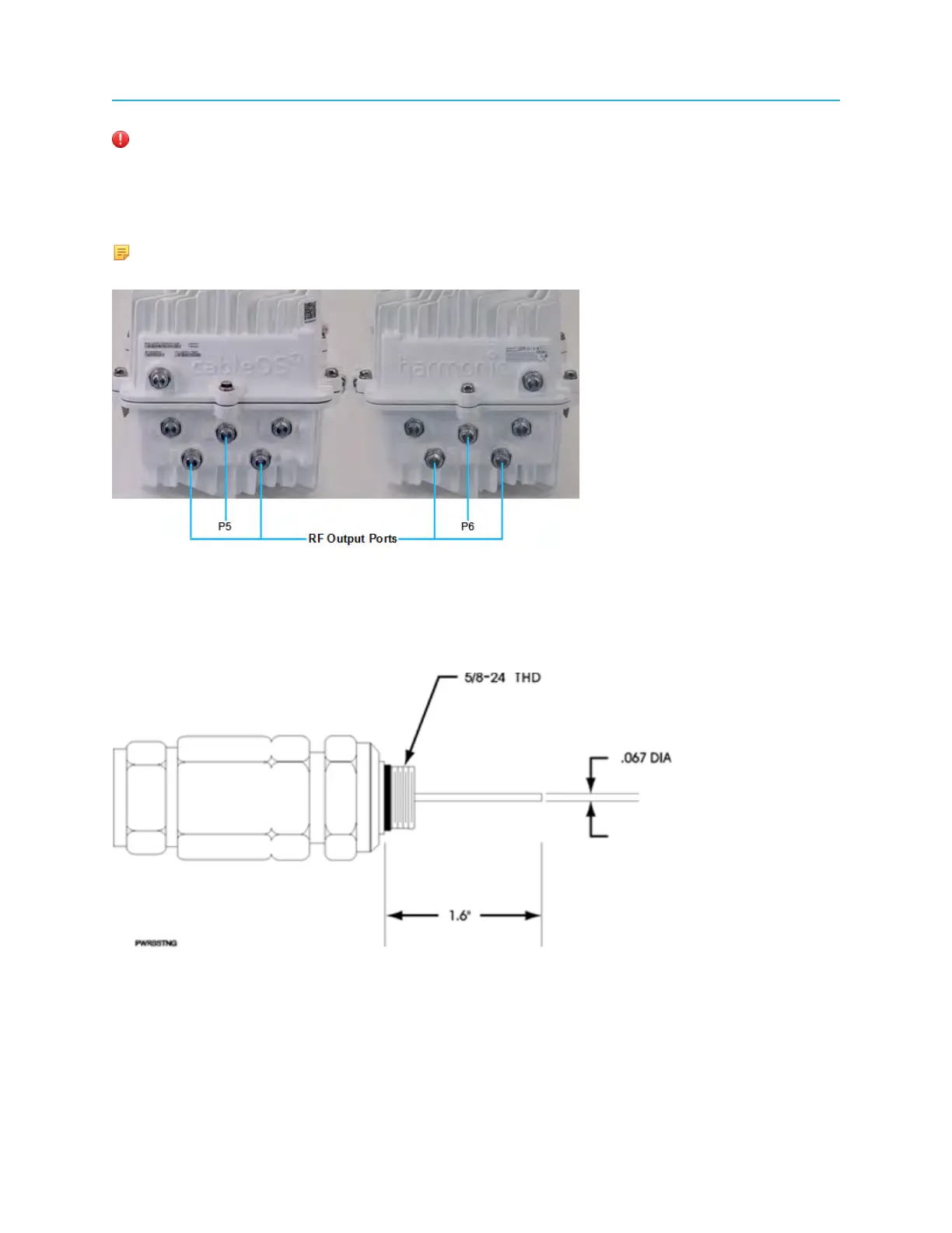
The coaxial cables require some preparation; preparation depends on the type of coaxial cable and cable
connector you use. Generally, the node housing accepts pin-type (stinger) connectors with a nominal
diameter of 0.067 inch. The center conductor (pin) must extend 1.6 inches from where the connector body
(not including the thread) mounts flush with the node housing.
Figure 4-4: Coaxial cable stinger connector
Guidelines
• Form symmetrical expansion loops in each cable and avoid sharp bends or kinks
• When the node is installed in a pedestal, cut and shape the RF coaxial cables to fit the node housing
RF entrance configuration
36