Chapter 6: Replacing field-replaceable items
Functional specifications
• Time to fully charge: 1.5 minutes
• Resilience to power interruptions
◦ Single RPD node: survives interruptions up to 4 seconds duration
◦ Dual RPD node: survives interruptions up to 2 seconds duration
• Field-installed and hot-swappable without disrupting the node's operation
Installation steps
1. Detach all the node lid bolts with the torque wrench and open the lid to expose the module slots.
2. Use a medium flat-blade screwdriver to set the correct voltage (noted on the RF tray) so as to match
the setting used on the standard power pack.
3. Hold the Buoy Power Backup module by its handle and carefully insert its lower edge (facing exterior
edge of the lid) under the fiber channel, aligning the power module's connectors with their mate
connectors on the lid motherboard.
4. Push the module firmly down into the lid motherboard connectors.
5. Secure the power supply module with the two mounting screws using a medium flat-blade screwdriver.
6. Close the node housing, strictly adhering to the Closing the Ripple-2 Node housing procedure.
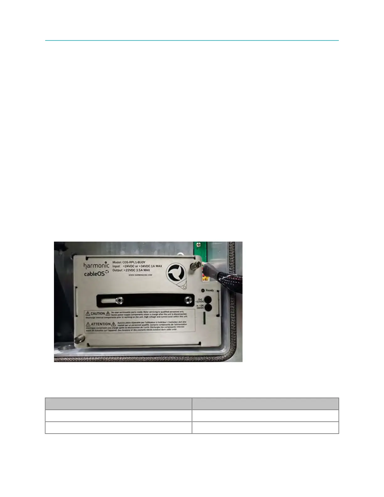
The picture below shows the Buoy Power Backup module installed in the right power supply slot of the
Ripple node housing.
Ready LED indications
The Buoy Power Backup module features a Ready LED that indicates the current charging and
operational status of the Buoy Power Backup module as listed in the following table:
LED Color and/or Pattern State Indicated
Green, flashing Charging
Green, steady Ready to protect
90