2-58 888-2629-200 10/6/10
WARNING: Disconnect primary power prior to servicing.
Section 2 Installation
Maxiva ULX COFDM Series
• J9 - Remote Analog Metering Outputs
NOTE:
The forward slash (/) in front of a signal name means active low. The signal
named "/INPUT 1" for example is activated by bringing that input low. Signal
names without the forward slash are considered active high. This convention is
used throughout the schematics.
2.15.1 Individual Transmitter Commands J3, J4 and J5
All control inputs use opto-isolators for surge protection. The opto-isolators are
powered by an internal +5Vdc from an isolation protection circuit.
All transmitter control functions (except Remote RF Mute, RF Switch Position A and
RF Switch Position B, which are active LOW or HIGH level input states) are
momentary ground switching and require the remote control equipment to sink at least
15mA to activate the function. The Pinouts of J3, J4 and J5 are listed in Table 2-12.
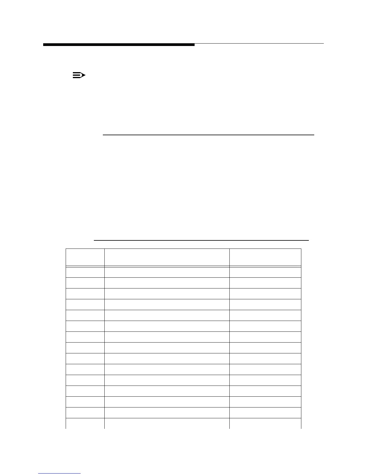
Table 2-12 J3, J4 & J5, Customer I/O Board, Remote Control Connectors
Connector
and pin #
Function Command Type and
Polarity
J3-1 GROUND
J3-2 TRANSMITTER_ON Pulsed LOW
J3-3 TRANSMITTER_OFF Pulsed LOW
J3-4 RAISE_POWER Pulsed LOW
J3-5 LOWER POWER Pulsed LOW
J3-6 /RF_MUTE
J3-7 GROUND
J3-8 EXCITER_ A_SELECT Pulsed LOW
J3-9 EXCITER_B_SELECTt Pulsed LOW
J3-10 EXCITER_AUTO_SELECT Pulsed LOW
J3-11 EXCITER_MANUAL_SELECT Pulsed LOW
J3-12 GROUND
J4-1 GROUND
J4-2 IPA_A_SELECT Pulsed LOW
J4-3 IPA_B_SELECT Pulsed LOW
 Loading...

