2-16 888-2629-200 10/6/10
WARNING: Disconnect primary power prior to servicing.
Section 2 Installation
Maxiva ULX COFDM Series
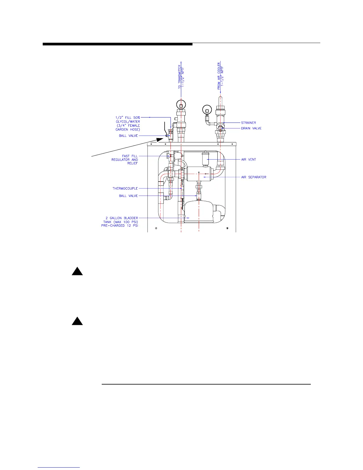
Figure 2-1 Suggested Charge Point
!
CAUTION:
DO NOT PRESSURIZE THE SYSTEM USING THE VALVE ON THE EXPANSION
TANK. THIS TANK HAS BEEN PRESSURIZED AT THE FACTORY AND IT SHOULD
NOT BE CHANGED.
!
CAUTION:
IF THE SYSTEM IS INITIALLY CHARGED WITH WATER DO NOT ALLOW THE
SYSTEM TO BE EXPOSED TO TEMPERATURES BELOW FREEZING. FREEZING
WATER IN THE COOLING SYSTEM MAY RESULT IN DAMAGE TO THE SYSTEM
COMPONENTS.
2.5.7 Pump Module & Heat Exchanger Electrical
The electrical installation of the heat exchanger and pump module unit should be in
accordance with the National Electrical Code and any local codes and regulations. The
incoming power supply is either 208-240V or 380-415V, 3 phase 50/60Hz. Fan and
Charge/Fill
Point