4-10 888-2629-200 10/6/10
WARNING: Disconnect primary power prior to servicing.
Section 4 Theory of Operation
Maxiva ULX COFDM Series
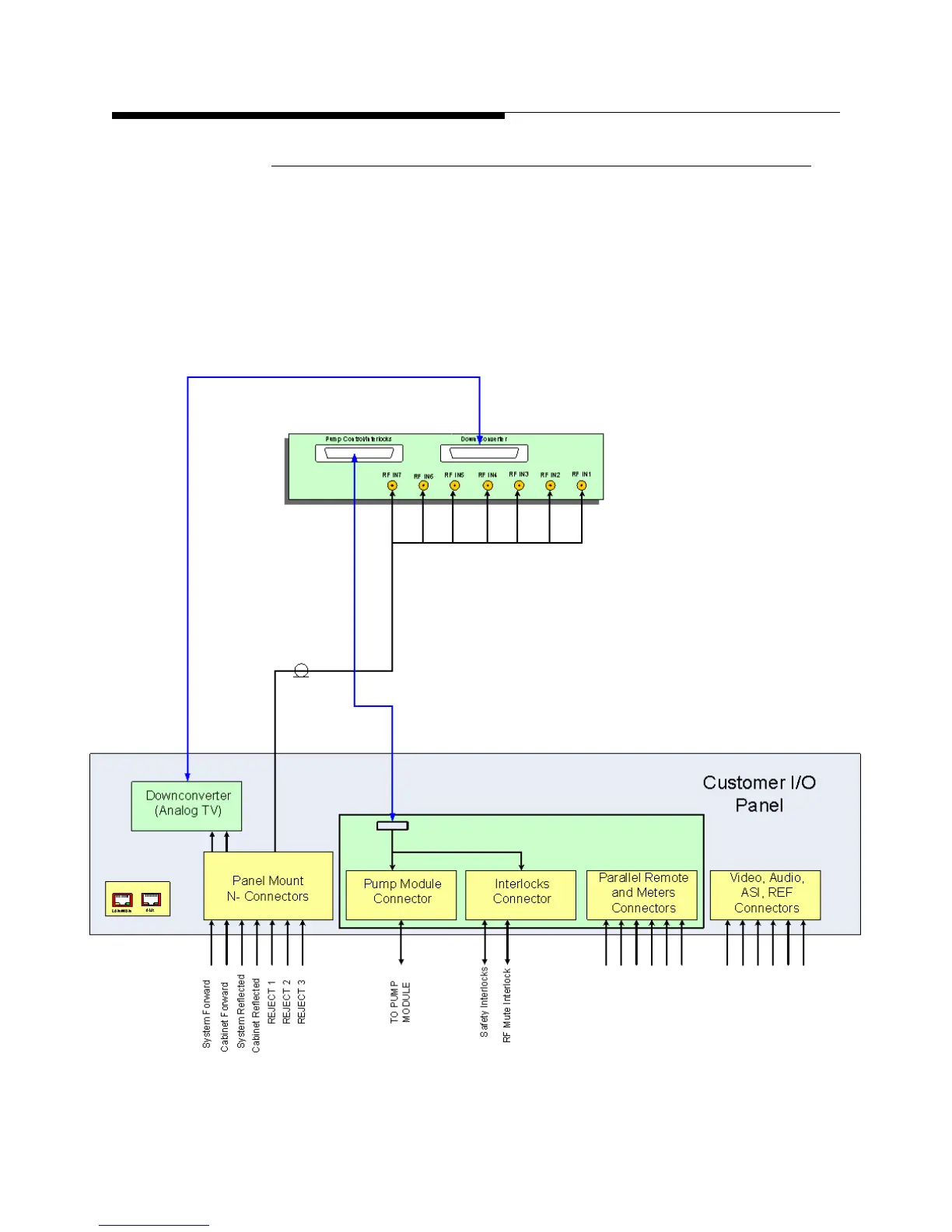
4.4.3.3 RF Detector/Pump Control/Interlocks Card
The RF detector/pump control/interlocks card is located in the TCU. It is made up of a
main and daughter board. The card contains seven RMS detectors with adjustable trips
set by EPOTS (electronic potentiometers). Pump control and interlock wiring is
combined on one D25 pin connector J3. For analog transmitters the card also serves as
an interface to the analog down converter board via another D25 connector J2.
Figure 4-
5 on page 4-10 shows the RF Detector/Pump Control/Interlocks card connectors on the
rear of the TCU and how the board is connected to the Customer I/O board at the top of
the transmitter.
Figure 4-5 RF Detector/Pump Control/Interlocks Card
 Loading...

