10/6/10 888-2629-200 3-15
WARNING: Disconnect primary power prior to servicing.
Section 3 Operation
Maxiva ULX COFDM Series
3.7 Output Main Screen
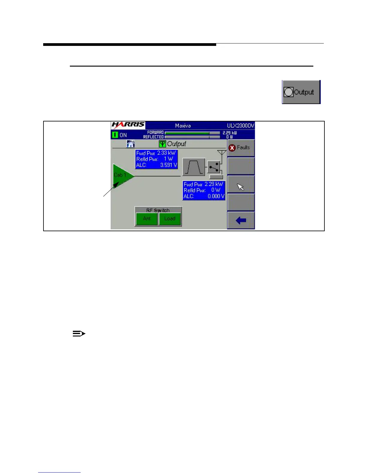
If you press the Output button on the HOME screen, it will take you to
the screen shown in Figure 3-10. The Output Menu structure is shown
in Figure 3-25 on page 3-29.
Figure 3-10 Output Screen
The main Output screen is has 3 main areas:
• RF Output System - This panel gives the total system Forward and Reflected
power, measured after the filter. It also has a VSWR and Foldback status
indications with backgrounds that are red for fault or yellow for warning. A
VSWR fault is indicated when the system VSWR is > 1.9:1. Foldback
warning is indicated when system VSWR is > 1.4:1
NOTE:
Both VSWR fault and foldback levels are adjustable via software.
• Power Amplifier Cabinet - Amplifier cabinet icons (triangle) give a status
indication of OK (green) or Fault (red) along with cabinet Forward and
Reflected power (before the filter) for each cabinet.
• Output Control - The control area at the bottom of the screen is used to
control an external RF switch so that the transmitter can be switched from
Antenna to the Test Load. The diagram indicates the position of the RF
switch based on micro-switches located on the switch.
To Figure 3-11
To Figure 3-4
Cabinet Indicators
 Loading...

