1-22 888-2629-200 10/6/10
WARNING: Disconnect primary power prior to servicing.
Section 1 Introduction
Maxiva ULX COFDM Series
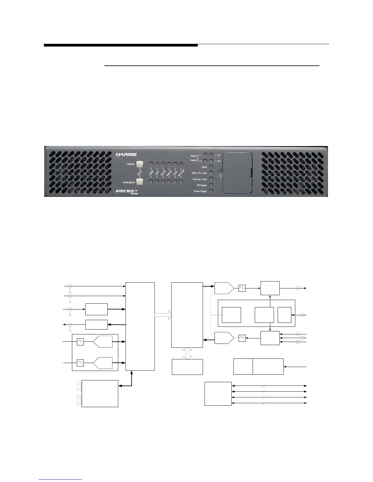
1.2.9 M2X Multimedia Exciter
The M2X exciter is used with the Maxiva ULX Series transmitter. This exciter is
described in a separate instruction book. A second hot standby exciter, and drive chain
switcher is available as an option. The exciter is controlled by the transmitter using an
internal CAN bus or Ethernet connection. Configuration, editing, diagnostics and
monitoring are possible using the front panel on the TCU display, or via Ethernet ports
provided with the exciter.
Figure 1-13 M2X Exciter Front
A single exciter unit drives the Maxiva ULX transmitter. The excellent quality and
stability of COFDM UHF signal output maximizes the TV transmitter efficiency,
improving performance and helping to reduce operating costs.
Figure 1-14 M2X Exciter Block Diagram
Video
Audio
A/D
A/D
DVB-ASI/
SMPTE-310
Rcvr & Cable
Equalizer
Modulator
FPGA
DUC/
Precorrector
FPGA
IF
PLL
A/D
RF IN (IPA)
RF IN (PA)
RF IN (HPF)
4
Analog Input
Option Board
D/A
1PPS
10MHz
Up
Converter
Down
Converter
RF
PLL
RF OUT
DSP
uC
10/100 BaseT
8
CAN
2
RS232
2
LVPS
AC
Universal
Battery
Backup
Option
GPS Ant
GPS
Option
10/100 BaseT
8
DVB-ASI/
SMPTE-310
Monitor
Cable
Driver
Transmitter
Interface Board
PFRU
Universal Exciter Platform
 Loading...

