2-62 888-2629-200 10/6/10
WARNING: Disconnect primary power prior to servicing.
Section 2 Installation
Maxiva ULX COFDM Series
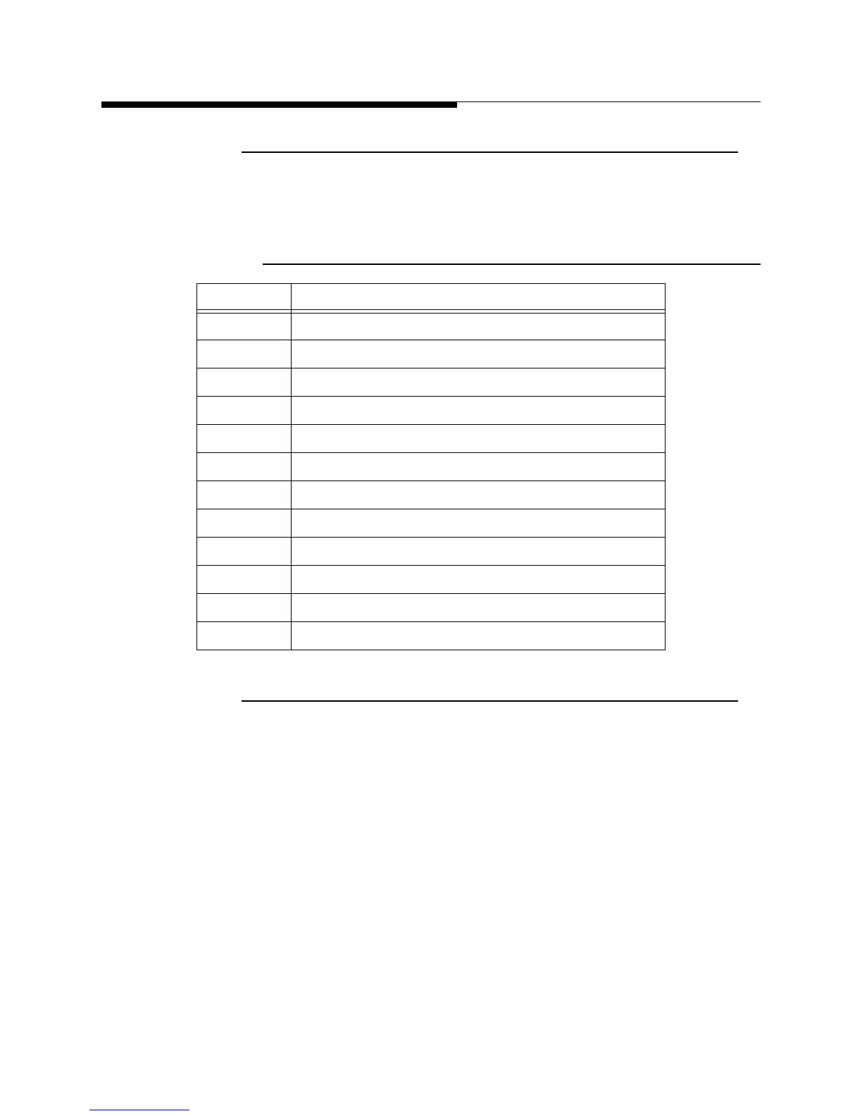
2.15.3 Individual Transmitter Metering, J9
Each analog metering output will provide 0 - 4.096Vdc output into a 400 ohm load
(where 3Vdc = Full Scale). The connections for J9 are listed in Table 2-14.
2.15.4 External RF Switch
The external RF switch connector is a 12 pin connector provided to allow control of
motorized switch that is external to the transmitter. The connections for J10 are listed in
Table 2-15.
Table 2-14 J9, External I/O Board, Remote Power Metering
Connection Metered Parameter
J9-1 SYSTEM_FORWARD_POWER
J9-2 SYSTEM_REFLECTED_POWER
J9-3 GROUND
J9-4 CABINET_FORWARD_POWER
J9-5 CABINET_REFLECTED_POWER
J9-6 GROUND
J9-7 IPA_A_FORWARD_POWER
J9-8 IPA_B_FORWARD_POWRE
J9-9 GROUND
J9-10 SPARE_1
J9-11 SPARE_2
J9-12 GROUND
 Loading...

