10/6/10 888-2629-200 2-11
WARNING: Disconnect primary power prior to servicing.
Section 2 Installation
Maxiva ULX COFDM Series
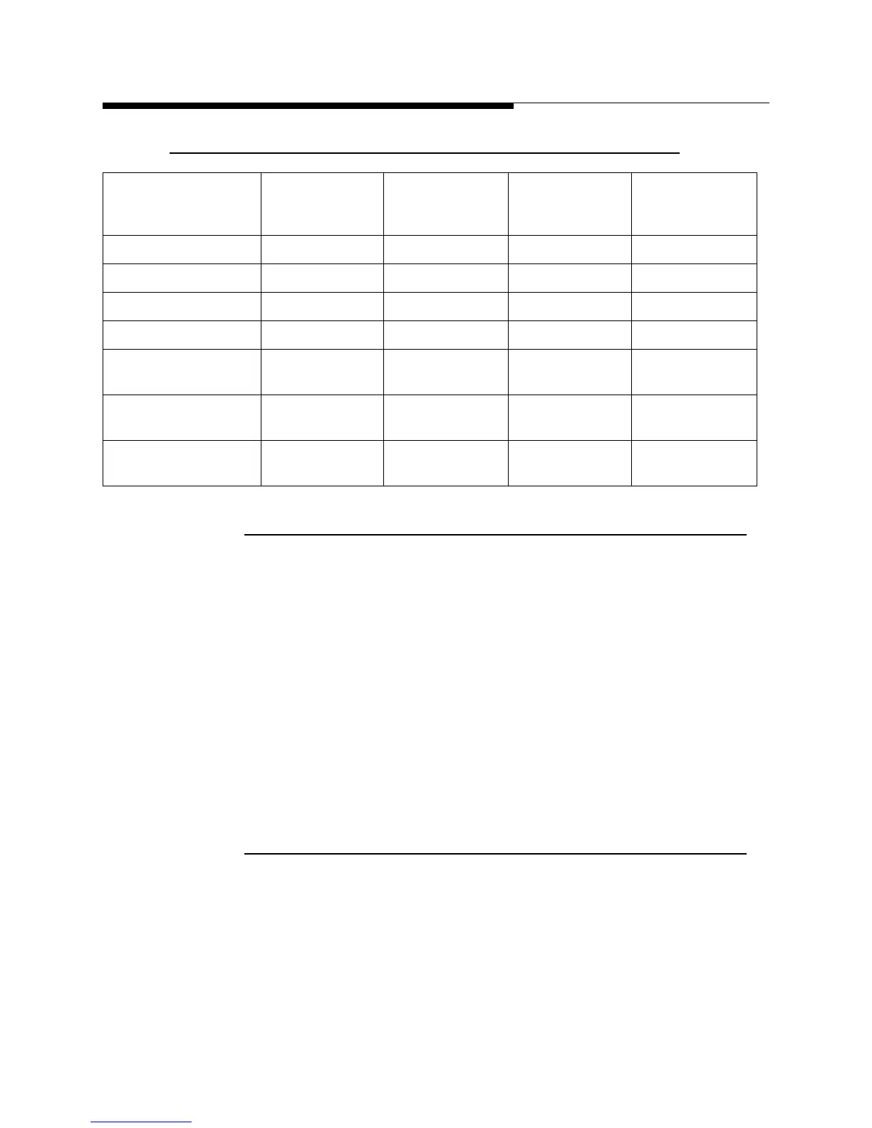
Table 2-5 Line length to Capacity Conversion Factors
2.5.3 Rigging Heat Exchanger & Pump Module
The equipment should be kept on the original pallet until ready for final instalaltion.
When using lifting belts ensure that a spreader bar is used and belts do not compress
sheet metal or plumbing. The exact method of handling and setting the heat exchanger
and pump module depends on the available equipment, the size of the unit, its final
location and other variables. It is the installer’s or mover’s responsibility to determine
the specific method of safely handling each unit. If possible, when the units arrive at the
site and are unloaded from the truck, plan to set and secure the heat exchanger in its
permanent place on its concrete pad or on the roof. The pump module (with control
panel) should immediately be moved to an indoor location. Refer to the section Figure
2.5.5 for heat exchanger & pump placement information. If required, complete any
required assembly of the unit. See paragraph 2.5.5, Placement of Heat Exchanger and
Pump Module
2.5.4 Initial Inspection
When the equipment and accessories are received, they should be immediately
inspected for shortages and damage. If the equipment has been damaged in shipment or
shortages are noticed, immediately notify the carrier and file a claim.
Nominal Type M
Copper Tube or
Hose Size
Feet to Gallons Feet to Liters Meters to
Gallons
Meters to
Liters
1-1/4 inch (OD hose) 0.064 0.242 0.210 0.794
1½ inch (ID tube) 0.092 0.348 0.301 1.140
2 inch (ID tube) 0.163 0.618 0.535 2.027
2½ inch (ID tube) 0.255 0.965 0.837 3.167
42 mm (OD tube)
39.6 mm (ID tube)
0.099 0.375 0.325 1.232
54 mm (OD tube)
51.6 mm (ID tube)
0.168 0.637 0.552 2.091
66.7 mm (OD tube)
64.3 mm (ID tube)
0.261 0.990 0.858 3.247
 Loading...

