4-2 888-2629-200 10/6/10
WARNING: Disconnect primary power prior to servicing.
Section 4 Theory of Operation
Maxiva ULX COFDM Series
4.2 Block Diagram Descriptions
See Section 1, Introduction, in this manual for a basic transmitter overview and block
diagram descriptions. Figure 4-1 gives a simplified block diagram. There is also a more
detailed overall transmitter block diagram at the front of the schematic package that
came with the transmitter. As a standard practice, the first page of a PC (printed circuit)
board schematic is also a block diagram of that board. Table 4-1 gives the basic Maxiva
model numbers and configurations.Using the model ULX-2300** as an example, the
model number breaks down as follows.
• U stands for UHF band.
• L stands for Liquid Cooled.
• X stands for Transmitter.
• 2300 stands for 2300 watts average power at the transmitter output before the band
pass filter.
• ** stands for the type of modulation. See Table 2-1 on page 2-1
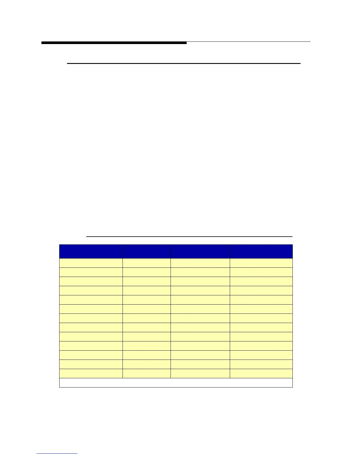
Table 4-1 Maxiva ULX COFDM Series Transmitter Models
Tx Models Cabinets PA Modules Output Power
ULX1100** 1 2 1100W
ULX-1700** 1 3 1700W
ULX-2300** 1 4 2300W
ULX-3400** 1 6 3400W
ULX-4400** 1 8 4400W
ULX-5500** 1 10 5500W
ULX-6500** 1 12 6500W
ULX-8700** 1 16 8700W
ULX-9500** 2 18(12+6) 13.4 kW
ULX-12600** 2 24(12+12) 12.6 kW
ULX17400** 2 32(16+16) 17.4 kW
ULX-18900** 3 36(12+12+12) 18.9 kW
ULX-26100** 3 48(16+16+16) 26.1 kW
NOTE: All power levels given in average output power before the bandpass filter.
 Loading...

