10/6/10 888-2629-200 4-15
WARNING: Disconnect primary power prior to servicing.
Section 4 Theory of Operation
Maxiva ULX COFDM Series
4.4.3.5 Customer I/O Card
The primary function of the Customer I/O Card is to interface between the internal
transmitter control system and all external or peripheral devices.The customer I/O card
is located in the TCU and is connected to the Customer I/O board connectors J13 and
J14 inside the cabinet top. For more detail on the customer I/O connections which can
be found on the customer I/O board on the top of the cabinet refer to section 4.5 on page
4-28 and to section 2.7 on page 2-28.
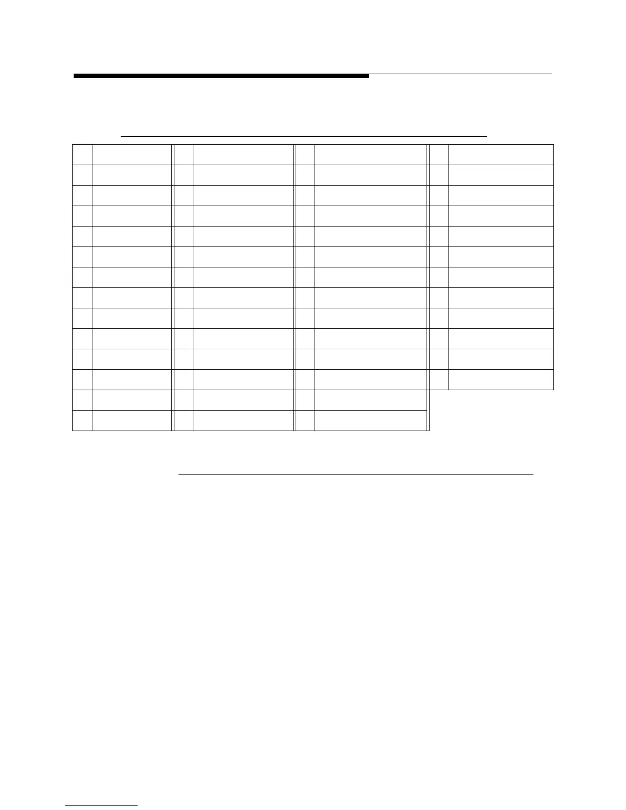
Table 4-5 PA Backplane Board BP 1 through BP 4 Control Busses
Pin Function Pin Function Pin Function Pin Function
1 VA+ 14 PA 3 Fault 3 27 Digital Output 5 40 Gnd
2 PA 1 Fault 1 15 PA 3 Present 28 Digital Output 6 41 PA 2 Output Power
3 PA 1 Fault 2 16 Gnd 29 Digital Output 7 42 PA 2 Sum Current
4 PA 1 Fault 3 17 PA 4 Fault 1 30 Digital Output 8 43 Gnd
5 PA 1 Present 18 PA 41 Fault 2 31 Gnd 44 PA 3 Output Power
6 Gnd 19 PA 4 Fault 3 32 TP3, Analog_Out 1 45 PA 3 Sum Current
7 PA 2 Fault 1 20 PA 4 Present 33 TP43, Analog_Out 2 46 Gnd
8 PA 2 Fault 2 21 Gnd 34 Gnd 47 PA 4 Output Power
9 PA 2 Fault 3 22 PA 1 On/Off 35 TP2, Analog_Out 3 48 PA 4 Sum Current
10 PA 2 Present 23 PA 2 On/Off 36 TP1, Analog_Out 4 49 Gnd
11 Gnd 24 PA 3 On/Off 37 Gnd 50 Gnd
12 PA 3 Fault 1 25 PA 4 On/Off 38 PA 1 Output Power
13 PA 3 Fault 2 26 Gnd 39 PA 1 Sum Current