10/6/10 888-2629-200 2-51
WARNING: Disconnect primary power prior to servicing.
Section 2 Installation
Maxiva ULX COFDM Series
2.14.1 Setting the Transmitter Flow Rate
STEP 1 Check the transmitter flow rate. Press SYSTEM>SYSTEM
COOLING>COOLING METERS. The first line shows the transmitter
flow rate.
STEP 2 Adjust the Flow Rate if necessary. Adjust the inlet valve for the
transmitter cabinet until the flow rate indicated on the GUI matches the
nominal flow rate of the transmitter model as shown in the table below
or as indicated in the Liquid Cooling System Layout drawing
NOTE:
Actual flow rate may deviate from nominal depending on site specifics like pipe
diameter, number of elbows, and run length. The flow rate must be above the trip
point level in order to prevent frequent faults and pump switches. Refer to the
Outline drawing and Plumbing layout drawing for more details.
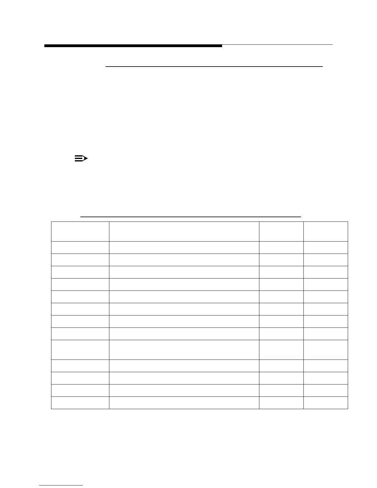
Table 2-11 Cooling System Flow Rates
MODEL NOMINAL TRANSMITTER FLOW RATE Trip Point
(LPM)
PA Modules
ULX-1100** 38 liters per minute 15 2
ULX-1700** 45 liters per minute 19 3
ULX-2300** 53 liters per minute 23 4
ULX-3400** 65 liters per minute 30 6
ULX-4400** 76 liters per minute 38 8
ULX-5500** 99 liters per minute 46 10
ULX-6500** 121.0 liters per minute 53 12
ULX-8700** 129.0 liters per minute 70 16
ULX-9500** 121.0 liters per minute - for 12 PA cabinet
65 liters per minute - for 6 PA cabinet
53
30
(12+6)
ULX-12600** 121.0 liters per minute - for each cabinet 53 (12+12)
ULX-17400** 129.0 liters per minute - for each cabinet 70 (16+16)
ULX-1890** 121.0 liters per minute - for each cabinet 53 (12+12+12)
ULX-26100** 129.0 liters per minute - for each cabinet 70 (16+16+16)