10/6/10 888-2629-200 5-27
WARNING: Disconnect primary power prior to servicing.
Section 5 Maintenance and Alignments
Maxiva ULX COFDM Series
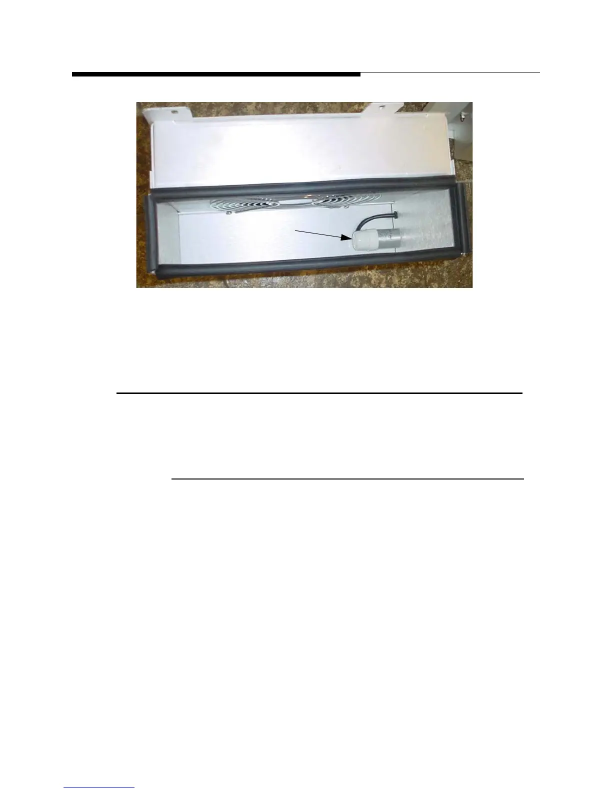
Figure 5-14 Fan Capacitor (inside fan enclosure)
STEP 5 Reverse the process to replace the fan.
5.10 PA Cabinet RF System Removal
Removal of the cabinet RF system is required if access to the PA backplanes, IPA
backplanes, combiners or dividers is needed.
5.10.1 RF System Removal
STEP 1 Turn off the transmitter. Remove all power and turn of main
breakers AC1 and AC2. Disable remote operation to prevent
transmitter from being reactivated.
STEP 2 Remove the cabinet fan assemblies. The fan removal sequence is
described in section 5.9 on page 5-25.
STEP 3 Loosen the clamp that holds the output coax in the flange (see Figure
5-15 on page 5-28).
STEP 4 Lift the output coax and inner conductor upward and away from the
flange (see Figure 5-15 on page 5-28). Secure the coaxial line so it is
out of the way.
STEP 5 Remove the four Phillips screws from the plate assembly at the top
of the cabinet.
Fan Capacitor
 Loading...

