1-18 888-2629-200 10/6/10
WARNING: Disconnect primary power prior to servicing.
Section 1 Introduction
Maxiva ULX COFDM Series
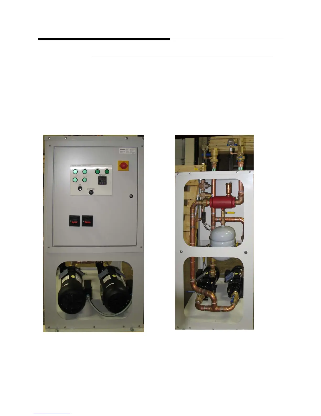
1.2.8.2 Pump Module/Heat Exchanger
The control panel/pump module and heat exchanger are separate units (each in a rack).
The control panel and pump module are self-contained in one rack and include a PID
(programmable logic controller), an expansion tank, air purger, pressure gauges, a
strainer and optional dual pumps operating in main/standby mode. The control panel/
pump module is designed for outdoor operation (some older models were suitable only
for indoor use). If used indoors the pump module and control panel should be located
near the transmitter if possible. The heat exchanger assembly is designed for outdoor
mounting.
Figure 1-10 Pump Module/Heat Exchanger
Pump Module Front
Pump Module Side
(Outdoor rated model shown. Indoor rated models
will not have full cowling over motors )