4-38 888-2629-200 10/6/10
WARNING: Disconnect primary power prior to servicing.
Section 4 Theory of Operation
Maxiva ULX COFDM Series
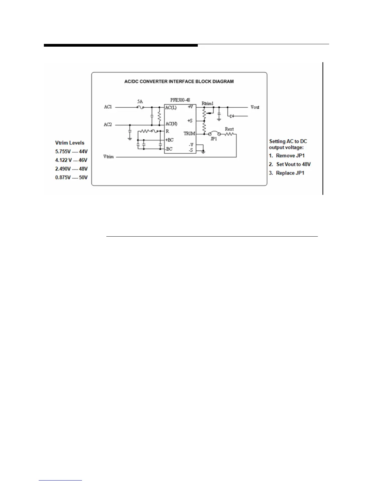
Figure 4-15 AC/DC Converter Interface Block Diagram
4.6.3.4 PA Monitor Board
The PA Monitor Board controls and monitors the PA module’s operation. All analog
parameters of the power amplifier are monitored and evaluated via the analog
comparators to generate the OK/FAULT logic signal, and the signal is sent to a CPLD
device to realize a pre-defined control logic algorithm. The fault and warning
information is displayed by the red/green LED’s in front of the PA, and the fault signal
is coded and delivered to the UCP in the Maxiva ULX transmitter via individual
separate wires. The overall control logic is done via a CPLD device and there is no
microprocessor on board and there is no serial communication designed into the PA
monitor board.
Only one fault can be detected at a time. If two or more fault conditions are detected
simultaneously only the highest priority fault is shown through the front panel LEDs
See Table 4-16 on page 4-39 for a description of the LED indications. The priority table
is designed to segregate fault that is most likely responsible for other faults that show up
simultaneously. The 3-bit code assigned to the fault with highest priority is sent to the
UCP. Following table shows priority assignment and corresponding 3-bit codes.
Priority, Code, Description
• 0, 000,No Fault
• 1, 001,Temperature Fault
 Loading...

