2-50 888-2629-200 10/6/10
WARNING: Disconnect primary power prior to servicing.
Section 2 Installation
Maxiva ULX COFDM Series
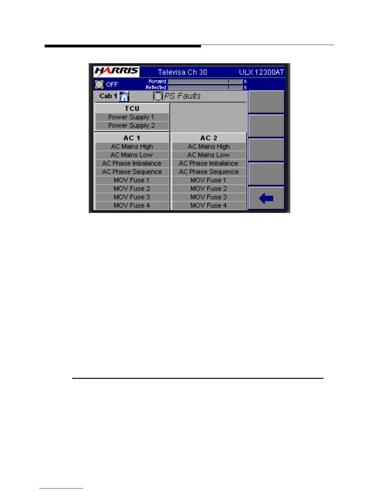
Figure 2-14 PS Faults Screen
STEP 7 Customize the transmitter System Setup.
SYSTEM>SERVICE>SYSTEM SETUP on the GUI. The System Setup
screen displays the settings for Sys Pwr Out, Center Frequency,
Modulation Type, AC Line Volt (VAC), Number of exciters, Number of
Cabinets and System Setup Entry. Touch the screen at each field to enter
the data pertinent to the setting. Once all the correct information in this
screen has been entered, press the CONFIG button. This screen is shown
in Figure 3-22 on page 3-26.
STEP 8 Customize the cabinet Setup. Press SYSTEM>SERVICE>SYSTEM
SETUP>CABINET SETUP on the GUI. Touch the screen at each field
to enter the correct data for CAB Pwr Out (W), Number of PA’s,
Number of IPA’s and Cooling Pumps (number present).
2.14 Final Cooling System Turn ON
Use the following steps to complete the cooling system turn on: