10/6/10 888-2629-200 5-47
WARNING: Disconnect primary power prior to servicing.
Section 5 Maintenance and Alignments
Maxiva ULX COFDM Series
card need to be replaced the following components should be set to the same values aas
the original board. The settings that should be checked are:
Blue jumpers:
JP1 1-2
JP2 1-2
JP4 2-3
JP5 1-2
JP-6 1-2
JP-7 2-3
JP-8 2-3
Rotary Switch (Cabinet ID S1):
Switch should be set to 1 for cabinet 1, 2 for second cabinet, etc.
DNLD/VT100 (toggle switch S2):
Set to VT100 if VT100 is connected to RS-232 port.
NOTE:
If the MCM card is changed the flash drive card should be removed from the old
board and installed in the new board. This will allow the system to retain previ-
ously stored calibration values.
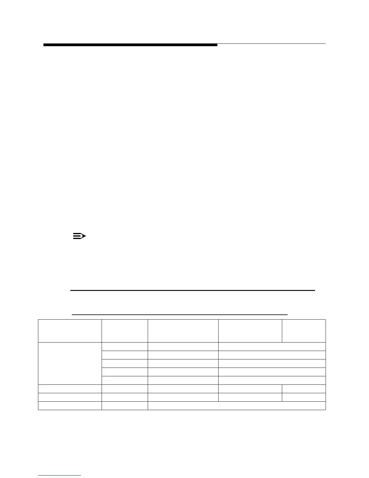
5.12 Typical Test Equipment
Table 5-3 Recommended Test Equipment
Equipment Type Manufacturer Model Number Options
Harris Part
No.
(if applicable)
TV Spectrum Analyzer R&S ETL ETL-B203 RF pre-select.
FSL-B4 OCXO Ref. Freq.
FSL-B7 Nar. Res. Filters
ETL-K220 ATSC Demod.
DIV7 ETL-K208 Meas. Log
Demodulator R&S EFA instead of ETL
Spectrum Analyzer Agilent 4402 instead of ETL
Power measurement Agilent E44182B power meter with E9300B sensor, 100 uW to 3 W
 Loading...

