3-2 888-2629-200 10/6/10
WARNING: Disconnect primary power prior to servicing.
Section 3 Operation
Maxiva ULX COFDM Series
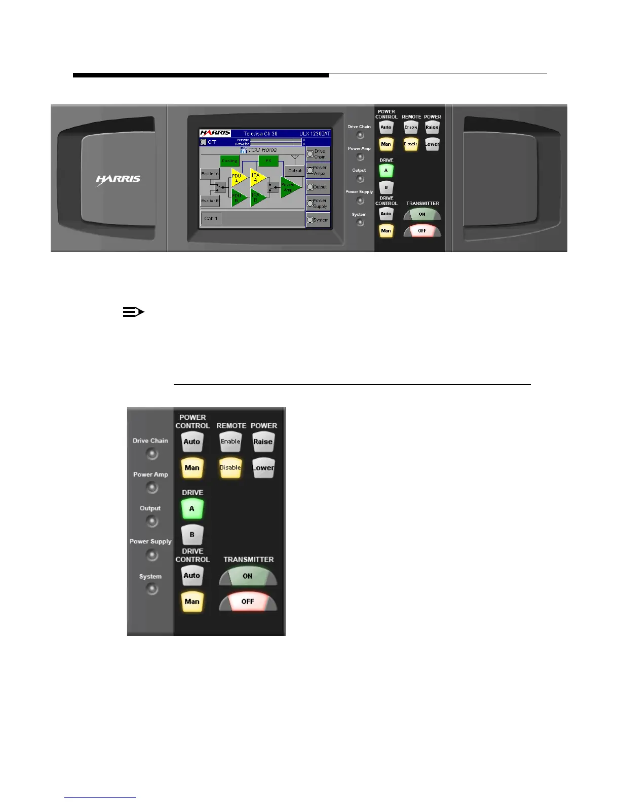
Figure 3-1 Transmitter Control Unit (TCU)
NOTE:
A similar set of GUI screens is available via web browser with an ethernet net-
work connection and the optional eCDi hardware interface.
3.2.1 Hardware Control Buttons
To the right of the touchscreen, there are 6 pairs of
hardware control buttons which are part of the front
panel overlay. Located to the left of the buttons are
Status LED’s which are green under normal, no
fault conditions. The hardware buttons provide
immediate control of 6 main transmitter functions:
a. Power Control - Auto/Manual
b. Remote - Enable/Disable
c. Power - Raise/Lower
d. Exciter - A/B
e. Drive - A/B
f. Transmitter - On/Off
The Status LED’s light amber (yellow) for a warning and red for a fault condition in the
transmitter subsystems. LED’s light green if the sub-system is normal. This provides
quick sub-system status information without having to be familiar with a menu
structure.
SYSTEM
 Loading...

