4-16 888-2629-200 10/6/10
WARNING: Disconnect primary power prior to servicing.
Section 4 Theory of Operation
Maxiva ULX COFDM Series
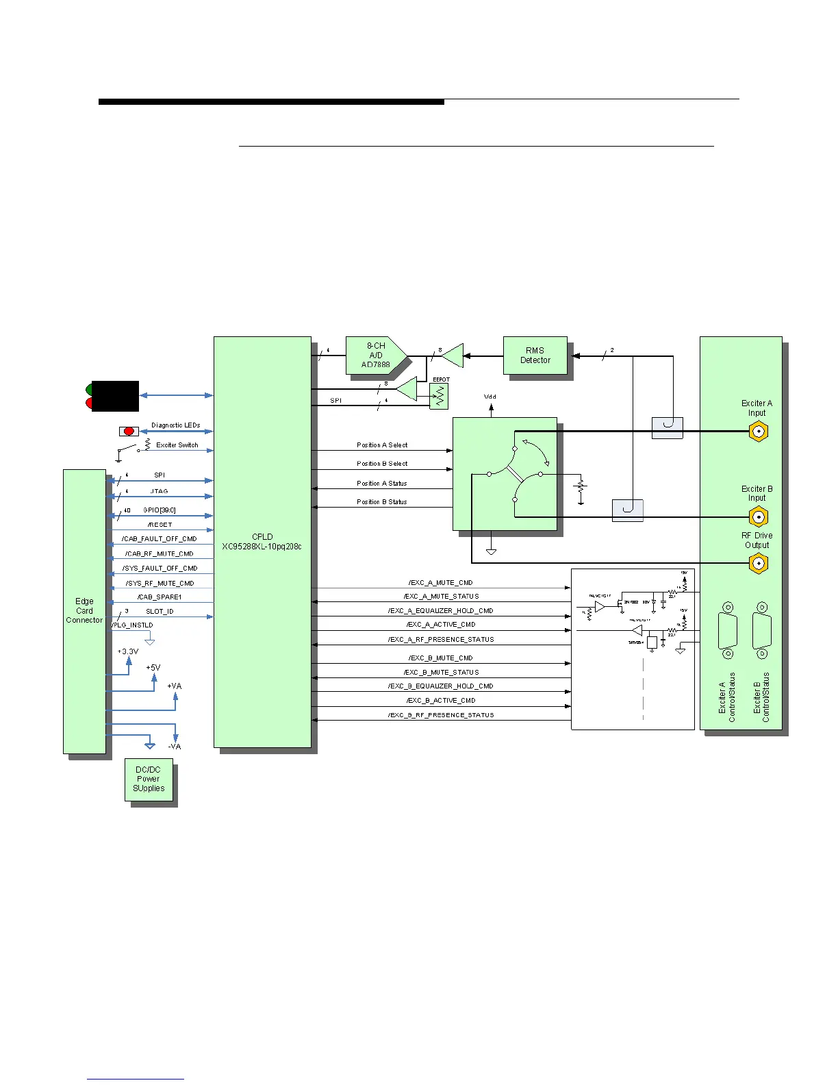
4.4.3.6 Exciter Switcher Card
The exciter switcher card in the main cabinet TCU controls exciter switching with a
board mounted relay. It includes 2 RMS detectors with adjustable trip points that use
EPOT’s to monitor exciter power. There are control and status interface connectors J1A
and J1B that go to exciters A and B respectively.
Table 4-6 shows the signals on the pins
of connector J1A. The simplified block diagram for the exciter switcher card is given in
Figure 4-7.
Figure 4-7 Exciter Switcher Block Diagram