4-36 888-2629-200 10/6/10
WARNING: Disconnect primary power prior to servicing.
Section 4 Theory of Operation
Maxiva ULX COFDM Series
4.6.3.3 PA PS (AC/DC) Voltage Select Path
Each PA and IPA has eight AC/DC converters (power supplies) which supply voltage to
the drains each power amplifier FET. Depending on the RF frequency of operation, the
power supplies can be set for 44 Vdc, 46 Vdc, 48 Vdc or 50 Vdc. The power supply
output voltage select path, from the MCM board in the TCU to each power supply in
each PA and IPA module is shown in Figure 4-14 on page 4-37. The PA voltage select
path from the MCM board in the TCU to the IPA and PA backplanes, shown with bold
lines in figure Figure 4-14, is carried on pin 7 of the 25 conductor Cabinet Bus. This
represents the only use of the cabinet bus in the Maxiva transmitter.
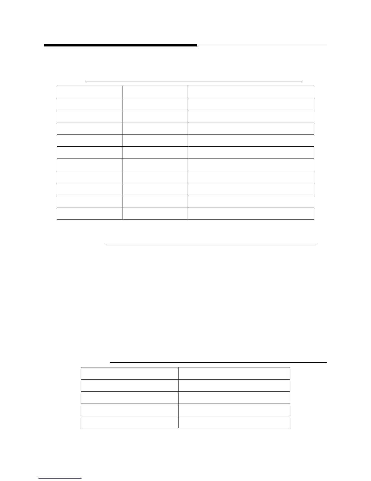
Table 4-14 PS Connector Pin Assignments
Pin Signal Description
1 AC1 Input, 3.4A, 240VAC fused at 5A
2 NC Not connected
3 AC2 Input, 3.4A, 240VAC fused at 5A
4 NC
5 NC
6 GND Ground
7 GND Ground
8 DC Trim Input, 6.49K ohms, 0.75VDC to 6.0VDC
9 DC Source Output, 0.4A, 50VDC
10 DC Sample Output, 9.09 Ohm, 50VDC
Table 4-15 PA Module Power Supply Output Voltage Control
PA_Voltage_ Select Voltage Power Supply Output Voltage
5.755 Vdc 44Vdc
4.122 Vdc 46 Vdc
2.490 Vdc 48 Vdc
0.875 Vdc 50 Vdc
 Loading...

