4-26 888-2629-200 10/6/10
WARNING: Disconnect primary power prior to servicing.
Section 4 Theory of Operation
Maxiva ULX COFDM Series
4.4.8 Cabinet Bus
The cabinet bus connects the cabinet TCU (MCM card) to the IPA and PA backplanes.
The cabinet bus connections are shown in
Table 4-12.
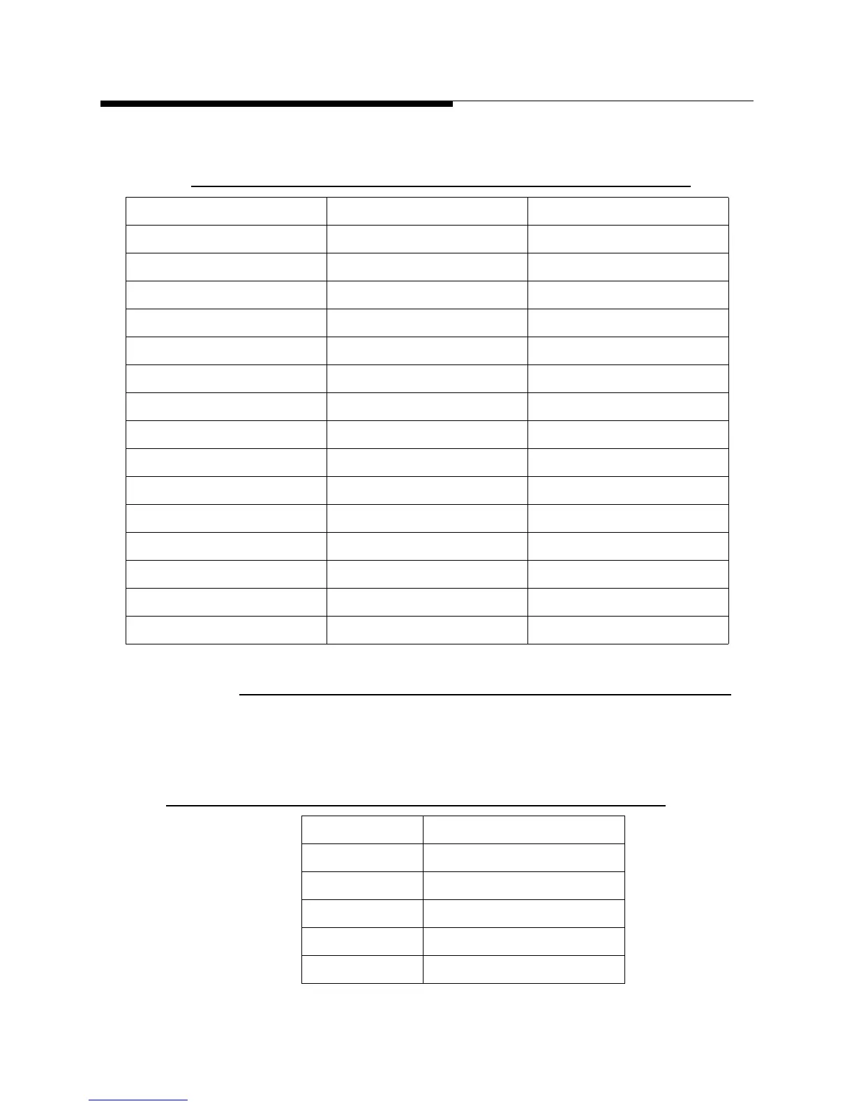
Table 4-11 MCM System Bus Connector
Pin Signal Description
1 SYS)_CAN_H CAN (5V) pass-through
2 /CAB_AC_LOW 3.3V CMOS Input
3 /SYS_OFF_CMD 3.3V CMOS I/O
4 /SYS_RF_MUTE 3.3V CMOS I/O
5 SYS_ALC 0-4.095V Analog I/O
6 SYS_PS_ADJUST 0-4.095V Analog I/O
7 /SYS_FAULT_OFF 3.3V CMOS I/O
8 SYS_SPARE1 3.3V CMOS I/O
9 /SYS_RESTRIKE 3.3V CMOS I/O
10 SYS_SPARE2 3.3V CMOS I/O
11 SYS_CTRLR_OK 3.3V CMOS I/O
12 /SYS_FAULT 3.3V CMOS I/O
13 SYS_SPARE3 3.3V CMOS I/O
14 SYS_CAN_L CAN (5V) pass through
15-25 GND
Table 4-12 Cabinet Bus Pin Assignments
Cabinet Bus Pins Function
1 through 6 No Connection
7 PA_voltage_select
8 through 13 No Connection
14 Through 24 Ground
25 No Connection
 Loading...

