4-8 888-2629-200 10/6/10
WARNING: Disconnect primary power prior to servicing.
Section 4 Theory of Operation
Maxiva ULX COFDM Series
4.4.3.1 MCM Card
Each TCU contains an MCM (master controller module) card. The MCM is a
microprocessor based controller used for all critical transmitter control functions. The
MCM cards in each cabinet TCU (in multi cabinet systems) are tied together via the
system bus. The system bus allows interchange of control and status information
between the main cabinet TCU and additional PA cabinets. The MCM is responsible for
maintaining life support operation when the PCM card is not operational. The system
bus connector (J6) connections are provided in Table 4-11 on page 4-26.
The cabinet bus connector (J5) has limited use in this transmitter. Pin 7 is the only
signal used in the cabinet bus. It sends the PA_voltage_select signal to the IPA and PA
backplanes, from which it is sent to the IPA and PA modules, where it controls the DC
output voltage from the eight AC to DC converters in each module.
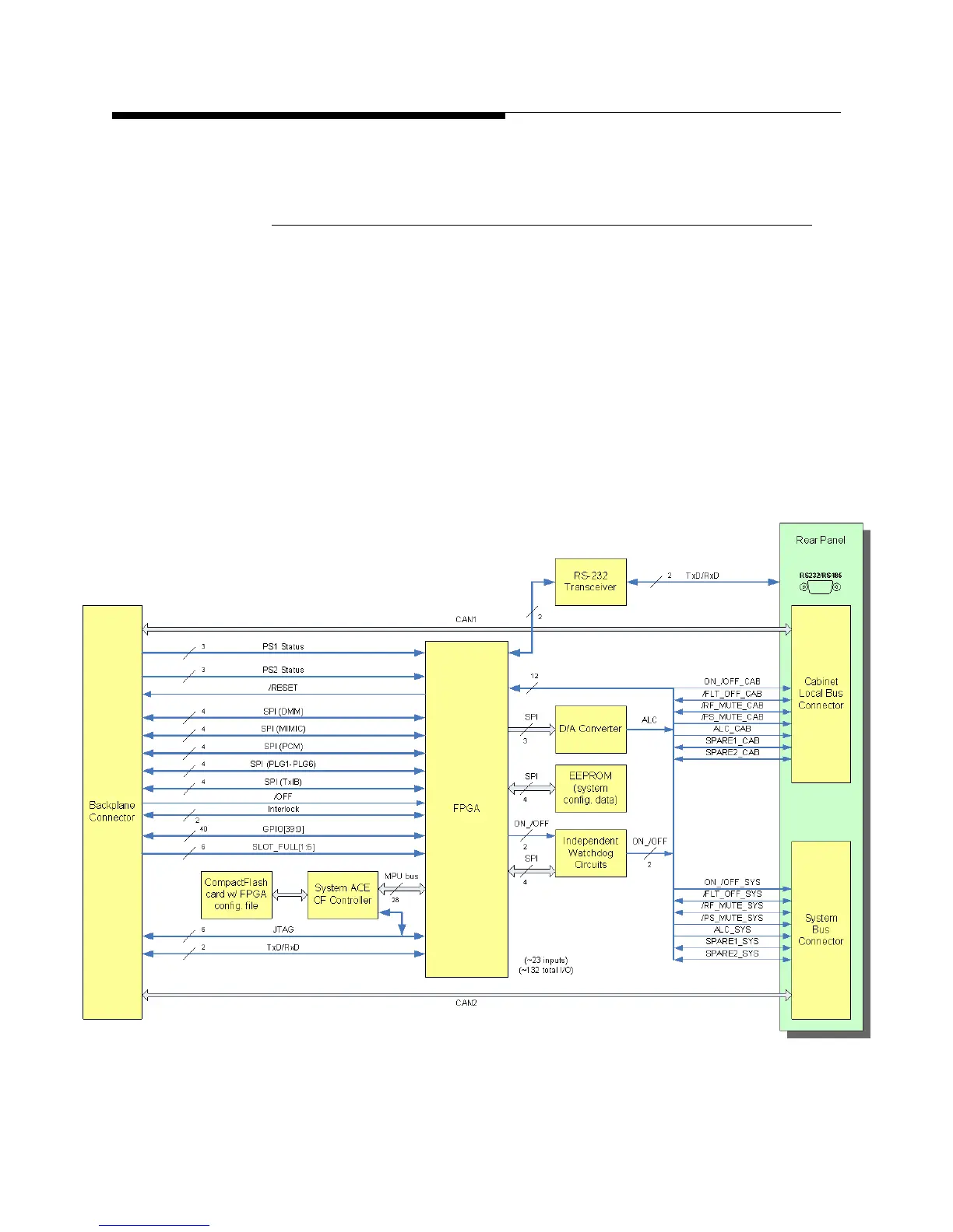
Figure 4-3 MCM Card Block Diagram
 Loading...

