3-26 888-2629-200 10/6/10
WARNING: Disconnect primary power prior to servicing.
Section 3 Operation
Maxiva ULX COFDM Series
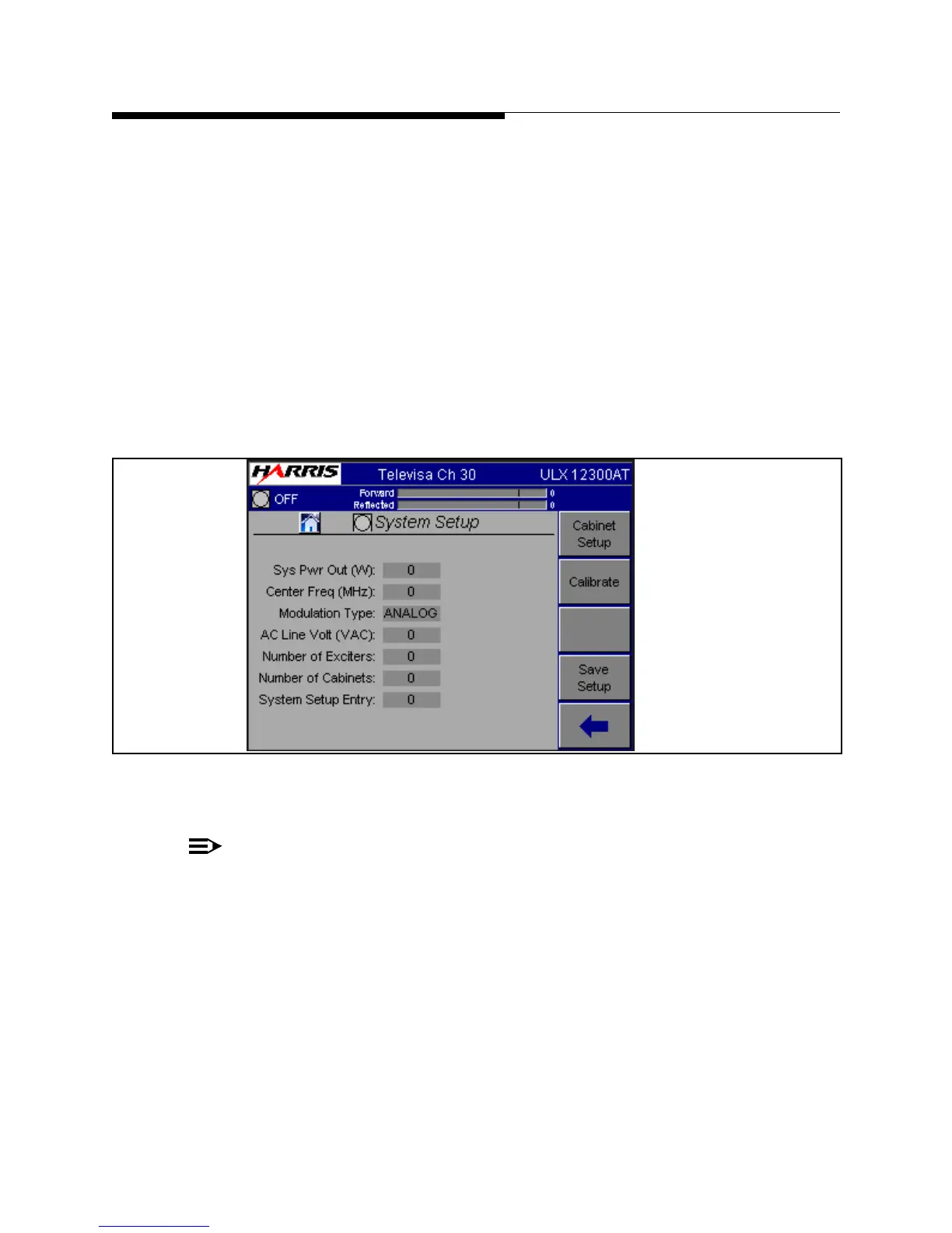
• Modulation Type: Select the system modulation type from the values displayed in
the box.
• AC Line Volt (VAC): Set this to the nominal AC line voltage at the transmitter site.
• Number of Exciters: Set this to either 1 or 2 depending on how many exciters are in
the transmitter.
• Number of Cabinets: Set this to the number of PA cabinets in the system.
• System Setup Entry: Enter a number from 1 to 8 in this field. For example if you
want to set up the transmitter for CH29 and store it in entry 3, you enter 3 in the Sys-
tem Setup Entry. This will recall the data for entry 3. If no data is there, defaults will
be loaded. Once all the calibrations for channel 29 are done you press SAVE SETUP.
This will save the data to entry 3.
Figure 3-22 System Setup Screen
NOTE:
The Save Setup button allows storage of up to eight setups for the purpose of
N+1 operation. All the calibrations for the transmitter are saved in the MCM
module. This means the transmitter can change to anyone of 8 channels and be
fully calibrated by simply recalling the set up entry. The N+1 controller will send
the set up the entry that needs to be recalled, as well as set the exciter frequency.
To Figure 3-23
To Figure 3-17
 Loading...

